
D-200 Automatic restoration project (re posted)
By
wheeledhorseman, in Wheel Horse Tractors
-
Similar Content
-
 By tractorboy79
I was looking around on ebay and noticed that hydraulic actuators from John Deere 312, 317, etc models appear to be Identical to a Gt14 or d series lift cylinder. My question is would a new cylinder from ebay be able to replace one that is on a gt14 or d series?
Images below of cylinders to show similaritys.
-
By BuffaloD200
'74 D-180
My friction disc in gone on my clutch. I saw the old post about making a new friction disc, so I'm not concerned about that.
I managed to remove the front clutch plate and double v-belt pulley. But I can't separate the two. When I took the assembly off the spiraloc washer popped off on its own. I HAVE READ THE MANUALS.
So I should be able to just remove the pulley from the front clutch and continue with step 4. The v-belt pulley is loose as all hell and flops around like a dead fish. It seems to be hung up on a ring or bearing race.
So my thoughts are grab a BFH or sparky the blue tip wrench.
Is there an unpublished step 3.5, or some trick?
-
By BuffaloD200
Hey all,
My '74 D180 has a lot of trouble pushing snow. Weighted tires, but nothing else at this time. I've found it gets stuck frequently and only one wheel spins. Do these tractors not have a limited slip/locker arrangement? How does everyone manage with the infamous one wheel peel?
-
By BuffaloD200
Hey all, I need to install a drive belt on my 75 D180 for my snowblower. I've looked through a bunch of D-series owner's manuals, and none seem to mention replacement procedure. The PTO pulley is fixed, save for engaging the PTO and there is minimal movement at the snowthrower pulley. There's no idler or tensioner as far as I can tell. Do I have to remove the PTO pulley? That seems to be a required service item.
Same question for my 80 D200 as well really.
Using the recommended 4L490W belt.
Thanks
-
 By ihatephones
I got a D-180 for $250, and the governor is messed up, the points won't open or close, and I took it apart and was being stupid and messed some stuff up in there, and now I need a new one.
Where can I get one that's not on eBay for $200?
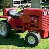
I also forgot to say it was a Kohler K482, and I'll throw some pictures of the tractor in as a treat.
-