Jump to content
sjoemie himself

Murray to IH 1568

Recommended Posts

wallfish

:text-yeahthat:

  • Like 1
  • Thanks 1

Share this post


Link to post
Share on other sites
 
sjoemie himself
On 10/29/2023 at 7:48 PM, Handy Don said:

functional and elegant

Thank you! I take that as a huge compliment from both you and @wallfish


On the subject of hydraulics, in which you both have quite some experience I would like to pick your brains.

I have, what I think are, all the components together now minus hydraulic lines.

Could you (and others are welcome to join in too ofcourse) confirm that this is indeed all I need?


Components are:

- hydraulic tank with breather/filler and gauge 

- in-line oil (suction) filter

- gearpump with added support bearing

- valveblock with pressure relief

     * 1 single acting valve

     * 1 double acting valve


Said valveblock has found a spot on the tractor. It does require the battery to be err.. relocated but we'll cross that bridge when we get there.

20231103_205059.jpg.316afa38f3fb0399d739f6942e2e5a7c.jpg


Very tight fit in the dashtower/console. I did not plan this but the valve fits with about 5mm (+/- 1/4") clearance.

20231103_205249.jpg.72bbd0bb90aff7440f973beca417c52f.jpg


20231103_205321.jpg.05bf8b8a0143704e1c6aa0e0ccb94c15.jpg


Not going to be easy to control the valve where it sits but the goal is to make a couple of hood mounted levers for that.

The original 14/1568 have the gearbox levers mounted there and I think it would be neat to try and mimic that but instead control the hydraulics with it.

img-10.jpeg.30b9951556dcab23b622c0d553333bc9.jpeg


Most things I do out of the top of my head but this idea required a sketch, I'm more of a visual thinker. Now that it's on paper it's a matter of choosing the right dimensions for the parts. One solid bar on which two bushings rotate, one for each lever and function. Seems simple enough but the devil is in the detail, or in this case the geometry. The valves sit in the heart of the tractor, quite low and will need to be connected via balljoints and pushrods to the levers. Need to be adjustable ofcourse.. probably many more sketches to come. 

20231103_205410.jpg.04da011d0a669b820de5df9fd5e0efce.jpg


Thanks for watching!


Greetings from the Netherlands, Mark 

Edited by sjoemie himself
Added info
  • Excellent 2

Share this post


Link to post
Share on other sites
 
wallfish
53 minutes ago, sjoemie himself said:

Components are:

- hydraulic tank with breather/filler and gauge 

- in-line oil (suction) filter

- gearpump with added support bearing

- valveblock with pressure relief

     * 1 single acting valve

     * 1 double acting valve

The components are there. I prefer the filter on the return instead of the suction to the pump. If the pump gets starved it will burn up.  But there are filters designed for the suction side.

The single acting valve does limit it to a lift only type of situation and weight of whatever it's lifting is what's going to push the fluid back to lower it. So it's power in only one direction, no down pressure. The cylinder needs to be single acting as well.

If you want multiple cylinders on a single valve there are selector valves available. Basically one valve can control 2 circuits but only one at a time by which ever way the selector valve is set. Just throwing that out there

  • Like 4
  • Thanks 1

Share this post


Link to post
Share on other sites
 
Handy Don

Firstly, the compliments have been well earned, not gifted!


Then...following onto @wallfish’s useful comments, I’ll add only two things:

- hydraulic lines -- I don’t know your pump’s maximum pressure or how you’ll set the pressure relief valve but hard lines (⅜” OD metal) and a 700+ psi working pressure here made it much easier for me to fit lines into tight spaces. That said, some of the bends meant that I had to disassemble more of the tractor than I’d hoped to fit them in. I used JIC connects with 37º flares with an alloy tubing commonly used for brake lines in the US. Working pressure is somewhat over 1,000 psi and burst is around 1,500. More pressure gets you more power but demands heavier tubing and stronger bending/flare tools! You already know that hard lines MUST be clamped down to avoid vibration that will kill them quickly at the connections. Going to soft lines,. Soft lines are thick and don’t bend well and can chafe so I avoided using them as much as possible. Where needed due to moving components, I was able to use 2-layer hose (it was overkill). I didn’t acquire tooling for hose-to-termination connections so I planned ways to use off-the-shelf hoses to avoid the cost of custom.


- control valves -- like @wallfish, I prefer two-way valves and I made extra sure to include a float function on one spool of my valve (it’s scavenged from a JD 425). It has proved invaluable--even for the simple task of gently dropping the front-mounted flail mower to rest on its caster wheels when shutting down the tractor (yes, a one-way can do this too!) but you also can rest the front lift arm on a jackstand and command “down” to get a quick front-end hoist for greasing or tire work! If you can exchange your valve without too much loss, I would give it serious thought. Plumbing for 1-way cylinders is marginally easier, true.


I started out with almost no knowledge of hydraulics and spent a lot of time schooling myself and asking questions of anyone I thought might be willing to answer with useful info. In one instance, I learned a bunch from a mechanic while we were both waiting in line at the hydraulic repair shop!

Edited by Handy Don
  • Like 1
  • Thanks 1

Share this post


Link to post
Share on other sites
 
wallfish
5 minutes ago, Handy Don said:


I started out with almost no knowledge of hydraulics and spent a lot of time schooling myself and asking questions of anyone I thought might be willing to answer with useful info

Same. Had absolutely 0 experience with hydraulics before building that back hoe but did tons of research and reading to learn about it. Definitely not a waste of time!


It's a bit expensive when it comes to hydraulic components so doing that research ahead of time will save you some time, money and aggravation in the end.  The practical experience of doing it and using it will undoubtedly teach just as much by time your done. It's a good day when you can apply what you learned and put it to practical use and then be able to share it with others.

One thing to search is "hydraulic fluid accidents" and click on the "images". Look at them and being scared of that happening should keep you safe by adhering to what you learned. Working with high pressure fluid can be super dangerous and knowing that will help avoid being one of those images. Don't take short cuts or use any parts not designed for those high pressures involved.

  • Excellent 2
  • Thanks 1

Share this post


Link to post
Share on other sites
 
sjoemie himself

Thanks gentlemen! I'll take everything you wrote into consideration when moving forward with the build.

The hardline vs hose question will depend on the amount of space I have left and indeed on how much I would have to disassemble the teactor to reach different components. 

One big advantage I have is that I can make the hardlines and hoses myself. My employer has all the hoses and fittings I could dream up and as an employee I get a good discount on all the stuff plus I don't have to pay an hourly rate because I'm allowed to do that myself after hours.


Regarding safety and high pressure; I have a good amount of respect for it and have seen the images. I can assure you I WILL NOT use any component that is not up to the task. 

This is probably the only part where I won't be making custom parts. Except maybe one barbed fitting on the low pressure/suction side of the tank going to the pump.


A new update might take a while since I'm away for the weekend and 'winter is coming' so weekday evenings in the shop are not as tempting as it is in summertime. 

  • Like 2

Share this post


Link to post
Share on other sites
 
Handy Don
On 11/4/2023 at 4:27 AM, sjoemie himself said:

weekday evenings in the shop are not as tempting as it is in summertime.

I can relate to that!

Share this post


Link to post
Share on other sites
 
Oldskool

As always, excellent execution.  

  • Like 1
  • Thanks 1

Share this post


Link to post
Share on other sites
 
sjoemie himself

Update time. Between cold weather, updating the workshop, training for my upcoming chainsaw certification, gf's horse stuff and working I managed to work on my mini 1468 again.


Been working on the levers for actuation of the hydraulic valvebody. I scrapped my original plan of having both handles on one axle and opted to make two seperate axles and stack them.

Although this will give the levers a bit of a different throw I'm not bothered enough by that fact to change my mind a go with my original plan.


Anyway.. 


Ordered some parts and turned a few bushings and a shaft.

The parts I ordered are a pair of weld-on toothed axles and shift-pedals. Both ment for a Zündapp moped.

20231203_191158.jpg.663e7469529299b437d4efbc5bbb09c4.jpg


This is how it's going to be assembled.

20231208_155649.jpg.4b3c811068fd725d2f35939b538545d6.jpg


Toothed ends got pushed in and welded into the longer shaft.

20231208_164301.jpg.79a7616831b8417be9af994cc3e67574.jpg


Welded the bushings to a piece of tube to make a housing in which the shafts will rotate.

20231208_163214.jpg.f39842eb41cde518ec00f8236d3f5f9e.jpg


Two part post because of difficulties with uploading more pictures at once.

  • Like 1
  • Excellent 4

Share this post


Link to post
Share on other sites
 
sjoemie himself

Took the assembled axles to the lathe to make a groove for a snapring.

20231209_145427.jpg.872d9ed1e80cb59599fe58e8237b9de6.jpg


Snapring installed.

20231209_144957.jpg.690ef92b6c621c119217ddc9655eb3e7.jpg


Made and welded the other end of the shaft and assembled it and the arm that will attach to the hydraulic valvebody. 

20231213_202959.jpg.cc6a0a9487b6cb57dd991084238c82b8.jpg


20231213_202943.jpg.0b3108fcb413920b561a4ae30e170a8c.jpg


Next I'll attach both shafts with somekind of spacer inbetween and a mounting flange so that I can (un)bolt the entire assembly to the tractor as one unit.

Hopefully I'll have the actuating bit done by the end of the week. We'll see..

  • Like 1
  • Excellent 4

Share this post


Link to post
Share on other sites
 
Pullstart
29 minutes ago, sjoemie himself said:

chainsaw certification,


Cool!  Great work Mark!

  • Thanks 1

Share this post


Link to post
Share on other sites
 
sjoemie himself
13 minutes ago, Pullstart said:


Cool! 


It will be cool if I'll pass the exam :pray:

  • Excellent 1
  • Thanks 1

Share this post


Link to post
Share on other sites
 
sjoemie himself

Almost there.. and don't worry. The handles are just temporary!


20231215_173130.jpg.659e991323a507a480ea57a80ce4dcf5.jpg


20231215_162920.jpg.c2c5ad44b89172084421b436dc26d91f.jpg


  • Excellent 5

Share this post


Link to post
Share on other sites
 
sjoemie himself

SquareQuick_2023122322326345.jpg.77d6108c4504e8e856d5ad2c48fddd75.jpg

  • Excellent 2
  • Heart 3

Share this post


Link to post
Share on other sites
 
sjoemie himself

Worked on the hydraulics again but now more on the aesthetic side of things. As mentioned before I wanted to disguise the hydraulic levers as gearshift levers. The original tractor has those mounted on the side of the hood so that's what I've tried to copy. Since the mechanical side of it worked I got to play with some metal to get it looking right.


First I had to cut out a piece of the hood. Plan was to attach the 'gearshift housing' to the hood but I later decided against that and to mount the housing to the steering column. So the hole cutting process was a bit of a two stage excercise. 


First try.

20231222_115247.jpg.c7e76ac2d77860193d065d85e9a4e9e6.jpg


Version two with mounting plate in place.

20231226_130020.jpg.edfcd76aaa8dcba469caf70f6ad975a3.jpg


After that I made the actual gear selector housing from bits of plate. 

20231226_172056.jpg.9883d02a0d737866e8a2da90924710ab.jpg


And made a cover plate to go on top.

20231227_151139.jpg.5a6f200c32dc88b607cd13a9fd3e3b05.jpg


20231227_152811.jpg.c4cd905f225fc7fcbd4ba85d0a50406f.jpg


Looks close to original with the right levers now in place. The outside one looks a bit stubby but it operates the valve just fine.. now atleast.. without any system pressure. We'll see how it feels under pressure. Easy enough to lengthen them a bit.


20231230_184744.jpg.22f6feed26ca6e003fa4d833a8c011a5.jpg


Screenshot_20240107_185011_Gallery.jpg.613e353517aafd28a4f28c77143b2dcb.jpg


Next up will be to clean up the ugly gap that is visible between the hood and the dash/steering column. I've been dreading this ever since I got the hood on the way it is now. Cause I want it to line up nicely to the steering column and the gear selector box while the hood also has to stay nice and straight (as it is now). Fingers crossed!

  • Excellent 6
  • Heart 2

Share this post


Link to post
Share on other sites
 
Handy Don
5 minutes ago, sjoemie himself said:

the ugly gap that is visible between the hood and the dash/steering column

Blasphemous suggestion: body filler! :hide:

  • Haha 2

Share this post


Link to post
Share on other sites
 
Oldskool

Awesome work as always

  • Thanks 1

Share this post


Link to post
Share on other sites
 
sjoemie himself
4 hours ago, Handy Don said:

Blasphemous

Yes! :P


4 hours ago, Handy Don said:

body filler

No! :angry-nono:


Surely SOME bodyfiller will be required but as little as possible if I can help it.

  • Like 2

Share this post


Link to post
Share on other sites
 
Pullstart

Another work of art, to this work of art!

  • Like 1
  • Thanks 1

Share this post


Link to post
Share on other sites
 
Maxwell-8
On 1/7/2024 at 6:53 PM, sjoemie himself said:

Worked on the hydraulics again but now more on the aesthetic side of things. As mentioned before I wanted to disguise the hydraulic levers as gearshift levers. The original tractor has those mounted on the side of the hood so that's what I've tried to copy. Since the mechanical side of it worked I got to play with some metal to get it looking right.


First I had to cut out a piece of the hood. Plan was to attach the 'gearshift housing' to the hood but I later decided against that and to mount the housing to the steering column. So the hole cutting process was a bit of a two stage excercise. 


First try.


Version two with mounting plate in place.


After that I made the actual gear selector housing from bits of plate. 


And made a cover plate to go on top.


Looks close to original with the right levers now in place. The outside one looks a bit stubby but it operates the valve just fine.. now atleast.. without any system pressure. We'll see how it feels under pressure. Easy enough to lengthen them a bit.


Next up will be to clean up the ugly gap that is visible between the hood and the dash/steering column. I've been dreading this ever since I got the hood on the way it is now. Cause I want it to line up nicely to the steering column and the gear selector box while the hood also has to stay nice and straight (as it is now). Fingers crossed!


miljaar, Sta ik hier toch altijd te kijken van de vakmanschap. Ik doe m'n best en heb nog niet veel ervaring maar als ik jouw werk zie, geeft me dat toch altijd moet om zelf ook wat vaker aan de slag te gaan met metaal. 


Knap werk!

  • Like 2
  • Thanks 1

Share this post


Link to post
Share on other sites
 
sjoemie himself

@Maxwell-8 Dankje! Leuk om te lezen dat ik als inspiratie kan dienen. Ik zou zeggen; gewoon proberen en doorgaan.

Hoe gaat het met jouw projecten?


@Maxwell-8 Thanks! It's nice to read that I can inspire someone. I would say, go for it and keep on trying.

How are your projects coming along?

  • Like 2
  • Excellent 1

Share this post


Link to post
Share on other sites
 
19richie66

Nice work as always. Really coming together. 

  • Like 1
  • Thanks 1

Share this post


Link to post
Share on other sites
 
sjoemie himself

Hey all.. I've been searching for a good (looking) seat for a while now but all the ones I find are either

- too big (i'm pretty slim)

- ugly

- too expensive 

- all of the above


Anyone on here that has experience in the seat making business who can point me in the right direction and or have tips and tricks to get a good looking a feeling seat?


Since I really like the original 1468 seats I would like to stay as close to that as possible.

S400700BA_L-500x500.jpg.5ea27fed55cf1c6c0c77389d1823c884.jpg


So my plan is to make a seat myself according to the following dimensions.

20240113_094333.jpg.4c8bcd297b27a23357c1c2243c2530a3.jpg


All help and input is more than welcome!

Edited by sjoemie himself
Typo
  • Like 1
  • Excellent 2

Share this post


Link to post
Share on other sites
 
ebinmaine
3 hours ago, sjoemie himself said:

Anyone on here that has experience in the seat making business who can point me in the right direction and or have tips and tricks to get a good looking a feeling seat?


I am not by a distant long shot an upholsterer. 


Trina and I did recover the seat frame on Cinnamon Horse C160-8 when we restored that a few years ago. 


2 things I can offer. 

1.  Do NOT  skimp on the cover material. Make sure it's rated and real world tested to both high and low extremes. 

I used a plain black that was Cold Temperance rated for use on Snow machines.  It's held up very well.  


2.  Do some literal sitting around when choosing the interior foam. 

My one mistake was using a piece of foam we had laying here. It is NOT dense enough. I have to use an extra cushion. The money I spent on the extra cushion should have been spent on denser foam.  


  • Like 3
  • Thanks 1

Share this post


Link to post
Share on other sites
 
sjoemie himself

Thanks @ebinmaine for the info. Useful to know for sure. I'm thinking vinyl like stuff they use for boat seats.. should be durable and weatherproof.

The foam I'll probably buy online somewhere (like the cover material) after digging up some more info from the seller(s).


  • Like 3

Share this post


Link to post
Share on other sites
 

Create an account or sign in to comment

You need to be a member in order to leave a comment

Create an account

Sign up for a new account in our community. It's easy!

Register a new account

Sign in

Already have an account? Sign in here.

Sign In Now

  • Similar Content

    • T-Mo
      By T-Mo-(Moderator)
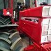
      Sorry for the late notice, but if anyone is near Fredricktown, Missouri, the 17th annual Cubarama is being held this weekend, starting Thursday, the 27th,  (set up day), Friday September 28, and Saturday September 29.  It's held the last weekend of September each year in Fredricktown and is for the Farmball Cub and Cub Cadet, but basically anything IH related.
       
      Fredricktown is about 80 to 90 miles south of St. Louis.
×
×
  • Create New...