Pullstart 59,735 #251 Posted February 2, 2020 Two frames have become one... for now. I’ll cut them back apart near the front and Z a piece in for a 4” rise, 8 1 Share this post Link to post Share on other sites
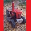
Pullstart 59,735 #252 Posted February 2, 2020 Last night after welding, then scraping junk, then letting it cool, I placed it on the floor of the shop. It is quite twisty, but has virtually zero deflection from my weight directly over the welded section bouncing on it. My structural integrity is key and I want it to be able to move a bit, but I know it needs more bracing than a conventional frame. I have some 3/16” thick angle that’ll be triangulated some how to help this monster stay true. Also, corner to corner I’m within 1/16” of square. I bet a factory frame was within that ballpark too! 3 1 Share this post Link to post Share on other sites
ebinmaine 63,167 #253 Posted February 2, 2020 1 hour ago, pullstart said: within 1/16” of square Share this post Link to post Share on other sites
Pullstart 59,735 #254 Posted February 2, 2020 I was watching a construction failures video and found this really great quote. 3 Share this post Link to post Share on other sites
SylvanLakeWH 24,155 #255 Posted February 2, 2020 46 minutes ago, pullstart said: I was watching a construction failures video and found this really great quote. And... with bridges...and tractor frames...that weight is dynamic, changing with the distribution, vehicle speed and direction / distribution of the weight load... (And although most of the time wind speed doesn’t impact our ‘s like it does a bridge, you never know with one of @pullstart‘s creations...) 3 2 Share this post Link to post Share on other sites
8ntruck 6,376 #256 Posted February 2, 2020 (edited) Last time I crossed the Ambassador Bridge from Windsor into Detroit, it had one lane backed up with semi trucks most of the way across waiting to get through customs. Sitting in traffic about mid-span, I was noticing how the oncoming trucks produced a bow wave in the bridge deck. Couldn't help but think that the original designers of the bridge had no way of anticipating that load case! Fortunately, they probably used a large safety factor in their design. Edited February 2, 2020 by 8ntruck 2 1 Share this post Link to post Share on other sites
Tractorhead 8,611 #257 Posted February 2, 2020 so the enforce of the welded section make absolutely sense in each direction i.m.h.o. Great job ! 2 1 Share this post Link to post Share on other sites
SylvanLakeWH 24,155 #258 Posted February 3, 2020 6 hours ago, 8ntruck said: Last time I crossed the Ambassador Bridge from Windsor into Detroit, it had one lane beacked up with semi trucks most of the way across awaiting to get through customs. Sitting in traffic about mid-span, I was noticing how the oncoming trucks produced a bow wave in the bridge deck. Couldn't help but think that the original designers of the bridge had no way of anticipating that load case! Fortunately, they probably used a large safety factor in their design. Live 3/4 hour from that bridge!!! It and the Mighty Mackinac Bridge were the two I had in mind when I posted above about dynamic loads on bridges... I too have witnessed that wave effect as well as during severe winds on the Mac... it is amazing the movement... Lets hope @pullstart loads his creation’s dump with the frame’s inflection capacitor design coefficient (I made that up...sounded cool) in mind... 1 3 Share this post Link to post Share on other sites
Pullstart 59,735 #259 Posted February 3, 2020 Honestly, the load of the dump will mainly be over the axle so I’m not concerned with bridge chaotic collapse to-do’s. However, I did just verify that the box when loaded will keep some weight over the front end! I’d hate to see (though it would be fun to see) Rylee tossed like a spoon full of potatoes in a middle school food fight! Today I worked with my father in law to replace a broken leaf spring on his truck. We used a couple pairs of leaves from an old Ford Highboy to replace both sides of the second leaf on his packs. That’ll be out of the shop soon enough and I’ll get back to frame work on the dump. 3 Share this post Link to post Share on other sites
953 nut 51,736 #260 Posted February 3, 2020 9 hours ago, pullstart said: I’d hate to see (though it would be fun to see) Rylee tossed like a spoon full of potatoes in a middle school food fight! Being a great gymnast she would land on her feet and take a bow. 1 1 3 Share this post Link to post Share on other sites
oilwell1415 563 #261 Posted February 3, 2020 (edited) 13 hours ago, pullstart said: Honestly, the load of the dump will mainly be over the axle so I’m not concerned with bridge chaotic collapse to-do’s. However, I did just verify that the box when loaded will keep some weight over the front end! Inner engineer at work again..... The dump bed is over the axle, but the driver used to be there and isn't any more and you have been talking about making it a two seater. If you've got 300 lbs sitting just in front of the bed you've added about 900 ft-lbs of bending moment to middle of the frame that wasn't there before. If you load 300 lbs in the dump bed that load will be carried by the rear axle until you hit the brakes. At that point its momentum will cause another bending moment concentrated in the middle of the frame. There's going to be a lot of load on that joint with two people riding and hitting the brakes with a load. I think an X brace across the bottom and centered on the joint would make a big difference in strength and stability of the joint under load. Part of me also says well a piece of 1" steel on the bottom to make the vertical flange 1" taller as well so that the weld, which will be very hard and brittle and not kind about fatigue, isn't the only thing absorbing the tension at the bottom of the frame. Edited February 3, 2020 by oilwell1415 2 1 Share this post Link to post Share on other sites
Pullstart 59,735 #262 Posted February 3, 2020 I am far from being done with the frame supports in any way... and your suggestions are very much appreciated! I forget about things like torque applied, braking pressure added, and things of the like! Rylee and I were both bouncing on it yesterday with still satisfying results. I did make sure to chamfer both inside and outside for maximum penetration and will likely plate the inside regardless. I do have a lot of 1/8” plate steel from 2-1/2”-6 or 7” wide, 8-12’ long. I could stitch a plate from front to rear on each side if needed, but I think a 8-10” long (wide) fish plate would be strong enough to hold the weight I’m planning on putting on it. Share this post Link to post Share on other sites
wallfish 15,931 #263 Posted February 3, 2020 what oilwell wrote Static load is one thing but prepare for all of the dynamic loads. Full blast bouncing over a good size bump with a fully loaded bed plus passengers all while braking and going down a hill will add some heavy forces in ALL directions. Not sure how you have the frame mounted to the trans now but raising it to use the lower holes of the trans mount section gives you the 4" height adjustment needed for the front and you can mount a lower frame to the bottom holes in the trans, connect them with triangle or X bracing to add strength to the middle and or go all the way up to the front. It doesn't necessarily need to be a WH frame as suggested earlier but a heavy angle steel frame will work. That also helps to eliminate the weak point of the WH trans mount although some added plate to it is still a good idea. (A lower frame can can also be attached to the trans at the cast axle squares and leave the top frame attached as the normal frame mounting does.) 3 birds with one stone? Or make it 4 birds and use the lower frame as the floor support for your feet too. Think I'm up to about a dollar and a half in $0.02 thoughts so far. LoL Sorry if this isn't helpful or it's annoying and it's not intended to override any of your plans or anyone else's. Just wish I was building one too and this is how a project gets figured out to work in Leicester. You can tell me to shut up and stop adding my $0.02 at any time. The wife does that all the time because it's a bad habit of mine. 1 1 1 Share this post Link to post Share on other sites
ebinmaine 63,167 #264 Posted February 3, 2020 I got to tell you all I'm really enjoying this thread. Part of it is because I'm just plain looking forward to seeing the construction of any given tractor but I really like the customs. As you can imagine it's getting me ideas and reminders about things that I need to mentally process on my own build when I finally start getting that put together in a few weeks. But most of all I'm really enjoying the back and forth between everybody about the 68 million ways this could be done. I don't mean that in any kind of a smart remark type of way. It's just that there are so many different directions this could take and many of them are structurally okay to do. @wallfish I'm not in any way speaking for Kevin but I for one would rather have you tell me 17 different ways to do something instead of me forgetting one little thing. @pullstart I realize you already have a pretty good idea of what's going on in your head about how to build this thing. I also work in an industry where Dynamic Loading is something I deal with every single day. Design it heavier than you think you need it to be. Then add 20% to the strengths of that structure. I'm really looking forward to seeing this machine materialize..... 1 1 Share this post Link to post Share on other sites
oilwell1415 563 #265 Posted February 3, 2020 (edited) 2 hours ago, pullstart said: I could stitch a plate from front to rear on each side if needed, but I think a 8-10” long (wide) fish plate would be strong enough to hold the weight I’m planning on putting on it. A fish plate would be OK, but blocks the holes in the frame if you ever may need them. It also doesn't add as much strength as you would think it does. But if you put it on the inside and then filled the holes with weld it would do a lot more for strength and clean up the sides of the frame if you know you will never need them again. What I was thinking was something like this. Adding to the flange of the frame rail increases strength exponentially because it is farther from the centerline of the frame. Angle iron also tends to initially fail because it either twists or bows out ward. Then once the initial failure starts the geometry gets worse and worse until it really fails and gets ugly. Adding a simple cross brace eliminates both of the likely initial failure modes (twisting and bowing out) and adding a little to the flange improves the straight bending strength of the frame rail. Edited February 3, 2020 by oilwell1415 1 Share this post Link to post Share on other sites
8ntruck 6,376 #266 Posted February 3, 2020 16 hours ago, SylvanLakeWH said: Live 3/4 hour from that bridge!!! It and the Mighty Mackinac Bridge were the two I had in mind when I posted above about dynamic loads on bridges... I too have witnessed that wave effect as well as during severe winds on the Mac... it is amazing the movement... Lets hope @pullstart loads his creation’s dump with the frame’s inflection capacitor design coefficient (I made that up...sounded cool) in mind... The bridge that came to my mind was the Tacoma Narrows suspension bridge. It failed because the wind caused the deck to vibrate at it's natural frequency. The vibrations got so big, they destroyed the bridge. There are probably videos on line if you Google it. Lessons learned from that bridge had a large influence on the design of the Mighty Mac. Pull start - you can make the long frame stiffer by making it's vertical dimension bigger in the middle. 1/4 or 3/8 thick fish plates extending 10 or 12" either side of the frame splice. You can also add fatigue resistance to your welds by working them over with a needle de-scaler. 1 1 Share this post Link to post Share on other sites
ebinmaine 63,167 #267 Posted February 3, 2020 13 minutes ago, 8ntruck said: You can also add fatigue resistance to your welds by working them over with a needle de-scaler @pullstart Forgive my hijacking for a sec... Bill what does that do? I'm slowly learning about metal fab..... Share this post Link to post Share on other sites
oilwell1415 563 #268 Posted February 3, 2020 It's like shot peening, only not. It adds a compressive stress to the material and also causes vibration, both of which help with fatigue resistance. An easier and far less noisy method is to just anneal the joint with a torch. 2 Share this post Link to post Share on other sites
8ntruck 6,376 #269 Posted February 3, 2020 Ed - here is a little different explaination. Needle de-scalers act like a bunch of hammers that leave little dents in the surface of the metal. These little dents leave compressive residual stress in the surface of the metal. Fatigue cracks can only grow when tensile stress is applied, and fatigue cracks commonly start in the surface of a part. By leaving compressive residuals in the surface of a part, more load needs to be applied to the part before the material sees tensile stresses. This is what helps improve the fatigue life. Now, I'll start to pontificate. If you are satisfied with the above answer, stop reading. Fatigue failures are defined as failures resulting from repeated application of loads that do not produce stresses in a part that exceed the yield strength of the material. Steel has a fatigue limit. If the stresses resulting from repeated loading remain under about 23,000psi, fatigue failures will not happen. Other factors that affect fatigue failures include, but are not limited to, surface finish, part geometry, heat treatment, material defects, and material discontinuities (welds for example). Aluminum does not have a fatigue limit. Subjected to repeated loading, it will eventually fail in fatigue. Because of this, most critical aluminum parts have a service life, that when exceeded, the part should be replaced. The 737 that lost a section of the fuselage in flight over Hawaii was traced to fatigue cracksthat started in rivet holes in the skin near the forward door due to the repeated loads from cabin pressurization. Reinforcement was added in that area, and maintenance procedures improved to find these cracks before they reach a critical length. For the most part, any fatigue failures we see on a Wheel Horse will be the result of years of vibration, or some minor damage (a scratch, dent, or repair) in a critical location at some point in the tractor's life. The cracks in my two mower decks are the result of vibration. Hope this brief explanation helps. 4 Share this post Link to post Share on other sites
ebinmaine 63,167 #270 Posted February 3, 2020 3 minutes ago, 8ntruck said: Now, I'll start to pontificate. If you are satisfied with the above answer, stop reading Pontificate all you want. 99% of the time I'll keep reading. I tell people often, I don't want to know THAT it did something. I want to know WHY it did something... 2 Share this post Link to post Share on other sites
8ntruck 6,376 #271 Posted February 3, 2020 (edited) 1 hour ago, oilwell1415 said: It's like shot peening, only not. It adds a compressive stress to the material and also causes vibration, both of which help with fatigue resistance. An easier and far less noisy method is to just anneal the joint with a torch. Annealing with a torch generally releases residual stresses in the part. Most of the time annealing will not leave residual stresses behind. Edited February 3, 2020 by 8ntruck Share this post Link to post Share on other sites
Pullstart 59,735 #272 Posted February 3, 2020 3 hours ago, wallfish said: what oilwell wrote Static load is one thing but prepare for all of the dynamic loads. Full blast bouncing over a good size bump with a fully loaded bed plus passengers all while braking and going down a hill will add some heavy forces in ALL directions. Not sure how you have the frame mounted to the trans now but raising it to use the lower holes of the trans mount section gives you the 4" height adjustment needed for the front and you can mount a lower frame to the bottom holes in the trans, connect them with triangle or X bracing to add strength to the middle and or go all the way up to the front. It doesn't necessarily need to be a WH frame as suggested earlier but a heavy angle steel frame will work. That also helps to eliminate the weak point of the WH trans mount although some added plate to it is still a good idea. (A lower frame can can also be attached to the trans at the cast axle squares and leave the top frame attached as the normal frame mounting does.) 3 birds with one stone? Or make it 4 birds and use the lower frame as the floor support for your feet too. Think I'm up to about a dollar and a half in $0.02 thoughts so far. LoL Sorry if this isn't helpful or it's annoying and it's not intended to override any of your plans or anyone else's. Just wish I was building one too and this is how a project gets figured out to work in Leicester. You can tell me to shut up and stop adding my $0.02 at any time. The wife does that all the time because it's a bad habit of mine. John your input is always handy! Sometimes not applicable but still handy! The hydro control is in the way to move it up 4”. But if I build a new trans mount, I can move the frame up as far as possible there for sure! Crazy or not, I found a lot of inspiration for this frame at Rylee’s gymnastics meet this weekend. It was at a small arena in town and the “grandstand” area in the arena that would be where a stage is present during concerts had a huge triangulated speaker hanger up near the ceiling. I’ll work on a sketch to explain my idea. Please... no autographs on my Picasso. The red red section is the inspiration from the grandstand. If you added two vertical supports separating the length into equal thirds, then built kickers at a diagonal back to the previous third.... 1 Share this post Link to post Share on other sites
oilwell1415 563 #273 Posted February 3, 2020 38 minutes ago, 8ntruck said: Annealing with a torch generally releases residual stresses in the part. Most of the time annealing will not leave residual stresses behind. I didn't mean annealing would leave stresses behind, just that it was an easier way to increase fatigue resistance even though it does it in a different way. Share this post Link to post Share on other sites
oilwell1415 563 #274 Posted February 3, 2020 14 minutes ago, pullstart said: It may not be intuitive, but that isn't going to to anything to reinforce the weld. To reinforce the weld you need to have the truss extend in front of it to tie the front and rear halves of the frame together. You've also got to consider that the frame is not a cantilever beam as shown in your masterpiece. In engineering terms, it would be described as a simple beam that is supported from the bottom on each end and carries a load in the middle. 2 Share this post Link to post Share on other sites
oilwell1415 563 #275 Posted February 3, 2020 If you were only concerned about reinforcing the weld you would probably do something more like this, but you've got more to deal with, including the connecting between the transaxle and frame. Share this post Link to post Share on other sites