
Another foot pedal mod -C-175 Eaton 1100
By
pacer, in Restorations, Modifications, & Customizations
-
Similar Content
-
 By HVYTWR
I have this pedal kit that I started to build for my 312 Hydro. It should fit 300, 400, and 500 series tractors. It uses a stock brake pedal from an 8 speed tractor, The link arm slides over the brake pedal and is held in place with 3 set screws. This allows the pedal angle to be adjusted separately from the linkage adjustments for operator comfort. I started to build this kit and then decided that it wasn't for me because I have very long legs and a foot control is not comfortable for me. I believe this is a pretty good design, it fits up behind the factory belt cover with no modifications. You will need to add some sort of a reversing pedal and a return to neutral device if you wish. I purchased the pedal as new old stock for $60 so it has no wear inside the bore. Then with the fabrication I have done, and the misc supplies (heim joints, rod couplers, threaded rod, lock collar, etc.) I am asking for $150 shipped. I includes everything in the photos that show the foot pedal, I will partially disassemble it for shipping. Let me know if you have any questions.
My email is wagner.rsw@gmail.com
-
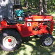
 By GT14
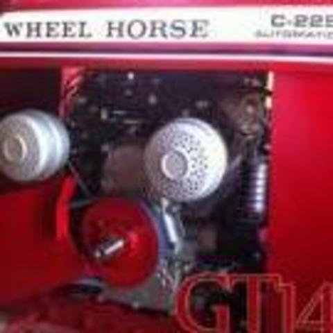
Finally got around to installing a foot control on my GT14
Used 5/16 mild steel rod, yoke and ball end.
Made a template with a coat hanger and then got to bending. Between the hydro cylinder supports and to the side of vertical lift arm.
View of entire rod.
Made the pedal from parts on hand. Large hinge and 3/4 square tube.
Added a filler piece of pressure treated wood in the steel frame.
Field trials coming up.
-