Pullstart 59,734 #1 Posted September 11, 2019 My log splitter is quite overkill. It has a 22 hp Predator, foot pedal operation, automatic return, etc... it’s a beast simply put. The cylinder is leaking as much fluid as what goes through it, practically. I could rebuild it, but the stroke is lacking significantly. It currently has a 4-1/2” bore cylinder with about 10” stroke. I realize that the diameter of the bore I what creates so much force. When I got the splitter about 6 years ago, it came with a new cylinder that is 3-1/2” bore and much longer stroke. Understanding that there will be fabrication involved to make this all fit together, would Imlove too much pressure on the ram by stepping down to 3-1/2”? I could gain much more stroke and fit a much longer log in the splitter as well. Also, I realize that the speed would increase too. I re-built the wedge a year or two ago and it seems to split with much less effort, which tells me I shouldn’t worry.... but if I put this together and it doesn’t work, I will be dead in the water because what’s there needs to be cut apart. Share this post Link to post Share on other sites
Pullstart 59,734 #2 Posted September 11, 2019 Here’s a video explaining this behemoth of a splitter! I know, my videography skills are quite lacking! This is the reason I need the splitter in operation. Most all my firewood is this large! Share this post Link to post Share on other sites
ol550 829 #3 Posted September 11, 2019 If my calculations are close to right you would be loosing 3.14 square inches of surface. So if your system relief is #2000 then 2000 X 3.14 = 21965 pounds less force. Share this post Link to post Share on other sites
Pullstart 59,734 #4 Posted September 11, 2019 Ok, I found a calculator at baumhydraulics.com, but I’m guessing st pressure figures. Now, how do I determine how much pressure is needed? Share this post Link to post Share on other sites
Tractorhead 8,611 #5 Posted September 11, 2019 (edited) Hi kevin, easiest way to find out what force is needed for splitting, is to check the Oilpressure while splitting. The pressure of you Oilpump is a given base parameter in your case. Simply mount a pressure gauge in the Highpressure line by a Tee Note the pressure at begin of split, and you can calculate the force what is needed. than insert a piece of metal opposite to wedge and check the max. Pressure of Oilpump if needed. bring it to Block, and you know, what pressure your Oilpump can deliver. If you need less pressure, simply added a pressure valve in line. if you must increase the Pressure, you can once increase the hydraulic pressure, if allready a valve is in, or you need a bigger cylinder (diameter). the length is just too much, if your oiltank goes empty. Another Way to findout the needed pressure, you can also use a Hydraulic press ( mostly available in workshop for ballbearing mount) if you have that, cut a piece of wood and set a wedge on top and watch the gauge. note the pressure and you have it. But first way is more senseful. Normally 110 Bar or 1595 PSI will be enough to split wood. but more is sometimes a bit better😎 @ol550 you‘re right with your calculation. Use that calculator, you‘ve found and compare your cylinders. the pressure calculation was f=p*A Where is F = Force p = Pressure A = Piston surface but kevin, please take care, hydraulics can have pressure until 250 Bar, thas beeing about 3626 PSI. Use urgently hydraulic fittings, they last that pressure ! Edited September 11, 2019 by Tractorhead Addedtext Share this post Link to post Share on other sites
WHX?? 46,801 #6 Posted September 11, 2019 Only thing I know about hydraulics is larger diameter ram = more power but slower cycle time. Smaller = less power but fast cycle. Most splitters compromise to get both on a given pump and flow rate. For more calcs you need the pump capacity in GPM, pressure you intend to run at. The pressure you need to apply in tons is handy also. Length of the ram doesn't mean much other than having more time for a cold one between cycles! Longer rams need stouter push rods to avoid bending at extended strokes. Most always with splitters pump output is given @ 3600 RPM. I have a 22 ton and it does most every thing I ask of it but a 28-34 would be nice on occasions. Anymore than that knarly stumps get left in the woods and move on. Here's some basics. https://flodraulic.com/formulae/basic-hydraulic-formulas 1 Share this post Link to post Share on other sites
Tractorhead 8,611 #7 Posted September 11, 2019 (edited) A suggestion is also the cylinderspeed shall not reach 0,5m/sec, to safe the wear of gasket. sorry, means 16,52 ft/ sec Edited September 11, 2019 by Tractorhead Share this post Link to post Share on other sites
WHX?? 46,801 #8 Posted September 11, 2019 (edited) 34 minutes ago, Tractorhead said: A suggestion is also the cylinderspeed shall not reach 0,5m/sec, to safe the wear of gasket. Or lose a couple of fingers and toes! Ok now that I watched the lifting wood of wood in the truck a smart man, who just turned sixty and wishes he hadn't abused his body when he was your age, would hook the splitter to a horse and split right out in the woods. The mess stays in the woods also. With smaller pieces then young girls can get exercise tossing them into the truck taking out the back window. Did I not learn you anything Kev? When making wood plan on handling the wood as few times as possible. Yah the length of stroke on that contraption sucks...even most free standers can take 18 inchers and outdoor wood stokers can often take 3 footers. I personally would ditch the splitter, the saws, the gas, the oil, the outdoor wood, the bad back and the whole nine yards. Super insulate the house with the proceeds of said sale to be able to heat it with a bic lighter and use the time gained not making wood to extend cocktail hour and relaxing with the missus.... just sayin.....Did I mention I sell high efficiency furnaces? Edited September 11, 2019 by WHX24 2 1 2 Share this post Link to post Share on other sites
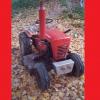
wheelhorseman 3,199 #9 Posted September 11, 2019 Kevin I personally would not put that cylinder on - less power and tiny rod - keep in mind the bigger the rod the stronger it is and the faster it returns (less oil is needed on the return trip because of the rod displaces the oil) here is the only picture I have of mine that I made from scratch it has a 5 inch bore and 2” rod and I wish the rod was bigger. It also has hydraulic tip for tipping the spitter up vertical. It has a old 10 hp long stroke Briggs on it and a 16 gpm 2 stage pump. 5 1 Share this post Link to post Share on other sites
WHX?? 46,801 #10 Posted September 11, 2019 (edited) I like it Lowell... I will like it even more if it's balanced well for easy hook up. Note the exhaust and the billiard ball fellas! Edit ... See the bulldog jack now... you need to bring that tractor to plow daze! Edited September 11, 2019 by WHX24 1 1 Share this post Link to post Share on other sites
Pullstart 59,734 #11 Posted September 12, 2019 So against better judgement, I hacked the old cylinder off yesterday. If anything, this will give me means to find the appropriate longer cylinder. I haven’t ever seen where any other splitter contains the cylinder and not the ram like this one and it seems to work quite well. My plan to prevent the ram from bending is to contain the cylinder and the ram plate with hopes of keeping one direction and less deflection. I have very little money into the whole set up, other than the engine, and the wedge seemed to relieve any stress on the system last time I ran this so I’m going to give it a whirl. The worst that can happen with this is it doesn’t work and I look for another cylinder. 1 Share this post Link to post Share on other sites
WHX?? 46,801 #12 Posted September 12, 2019 (edited) Looks like your push plate just floats on the main frame . I would suggest making or modifying the push plate to lock down to the main frame to prevent lateral movement and front support for the threaded shaft end. . Ears that wrap down under the frame?? Grind the top surface smooth. Secure the business end of the ram in a cage so it can't move side to side. Maybe even reuse/mod the one that's ther now? Fab a heavy bracket for the rear end to butt up against that angled frame. Edited September 12, 2019 by WHX24 2 Share this post Link to post Share on other sites
Pullstart 59,734 #13 Posted September 12, 2019 You’re pretty much on the same track as me. The whole ram pivots but I may end up turning it sideways some day across the back for full access. Share this post Link to post Share on other sites
Pullstart 59,734 #14 Posted September 12, 2019 This is the beginning of my cylinder block. Once I cut the piece in the mill, it’ll be drilled and tapped to bolt on to the mount. Once all fitup work is complete I’ll weld all the pieces as I assemble them. The last picture shows the way the splitter is mounted to the rig. I’d like to move the splitter further away from the engine and will some day build a kick up to help with heavy logs. Share this post Link to post Share on other sites
Tractorhead 8,611 #15 Posted September 12, 2019 Take a closer look at Lowell‘s, that has a guided Push plate. I like the idea, but if possible with a smaller Rod like you did, i would look if i can provide few ball bearings sideway’s, to prevent a twist of the push plate and even enlightened the movement itself. Share this post Link to post Share on other sites
Pullstart 59,734 #16 Posted September 12, 2019 So far, here’s where I’m at with the mount. Share this post Link to post Share on other sites
Tractorhead 8,611 #17 Posted September 12, 2019 Hi Kevin, i viewed your construction. doesn‘t look bad at all, but if i compared the Screws on the Cylinder and the screws you used for rearsupport, i would size them up. especially while you have a lever up to cylinder, they seems a bit to weak in my humble opinion. independently of grade, i would suggest, use the same size as the cylinder will be screwed together to keep the Load safe. just to be safe, about their working force, if you have a block at your Push plate and a full force will occur to the cylinder. maybe it is oversized, but better more safety at Hydraulics. i have also increased the Bolts on my HorseFEL from M12 to M16, because the M12 was to weak at high load and bends. i don‘t know, what size you’re realy using, and i know you have Metallfriction between your Parts, but it looks to weak (maybe just) at the Pictures. While i know metric sizes better i will it explain in metric, so if the cylinder is screwed with M12, i would preferr mount your Rearsupport also completeley in M 12. on the Pics it looks to me, the Cylinderscrews are M12 and your support screws are M8 in compare. That will maybe not last long and could be dangerous if full force occurs by max. Pressure and a block at the Push plate. just a suggestion. Share this post Link to post Share on other sites
Pullstart 59,734 #18 Posted September 12, 2019 Thanks for pointing that out Stefan! They are only 3/8”, but everything will be v-notched then welded with multiple passes I think that will hold, the bolts are pretty much just for mock up while I put things together. 1 Share this post Link to post Share on other sites
Tractorhead 8,611 #19 Posted September 12, 2019 The idea with screwing and welding in combination will be not bad. i would welding the Frame of Support and screwed the Lever, where hydraulicylinder was mounted. So if you Lever must be changed, later or because of a need for a stronger Cylinder, you are simply able to change it 👍 i love Servicefriendly Things, they quick can be improved. As i compared before, again in metric (im more familar with) it looks to me your supportlever was 16mm like 0,662 inches thick, same as the Bolt. If so, i would screwed it with 3x M12 as deep as possible. Ideal would be to screw it through with a Nut on backside in a higher Grade. for example a basic M12 Screw grade 8.8 can carry up to 16 Tons in pullforce. so 3x 16= 48 So 48 Tons of load are possible by 1x safety or 4,8Tons by 10x safety. Increasing on grade more(10.9) you are able to pull 25 Tons each. That will be an ability of 75Tons of pull force or 7,5To. By 10 times safety. 👍 and you are able to change the Lever when needed. If all last, you can it still use at it is and doesn‘t need to weld the Lever. more possibilities for later reworks. 1 Share this post Link to post Share on other sites
Pullstart 59,734 #20 Posted September 12, 2019 So much smarts in your head, Buddy! 1 Share this post Link to post Share on other sites
Tractorhead 8,611 #21 Posted September 12, 2019 We must have a beer together or better a Coffee 😂👍 sadly that we both traveling this year in same timeline opposite directions, i honestly will be curious to see you face to face. i guess this can be interesting conversations for both. but Next year ( have Kati convinced) we want to go to the Big Show... i got it straight in plan, just my job can be a critical point, but i will convince them also.😎 This is a must for me 😂 They know i infected by GT Virus, and healing isn‘t possible tells my Doctor..🤔😂 1 1 Share this post Link to post Share on other sites
Pullstart 59,734 #22 Posted October 6, 2019 Oooo shiney! I sometimes jump from project to project. A lot. Some parts came in from my father in-law’s laser shop. I can work on finishing the race now! 1 Share this post Link to post Share on other sites
Pullstart 59,734 #23 Posted October 6, 2019 These pieces are for the underside of the ram... to guide it along the I beam. They are as long as possible without interference. 1 Share this post Link to post Share on other sites
Pullstart 59,734 #24 Posted October 6, 2019 The holes in the front plate are to plug weld to the back plate, I’ll also chamfer and weld the entire perimeter. Hopefully the plug welds will double as grips for the log. I may even weld other grips onto the surface too. All the small pieces will brace the back of the ram. 1 Share this post Link to post Share on other sites
Pullstart 59,734 #25 Posted October 6, 2019 The ram is tacked up and this is my plan for bracing the back side. 1 Share this post Link to post Share on other sites