Stigian 1,234 #51 Posted January 6, 2018 I needed a better looking bracket to mount the transfer box shifter stick as the Quadzilla one was too big and very ugly. I'm sure you can guess which one is the new one Shifter bolted in. Still not quite sure where to mount it on the frame at this point, so I welded a couple of bolts to soe blue steel bar. Very long bits of bar With the "bolt ends" of the rods stuffed through the frame and bolted on the TB levers, I could see there was a fairly straight run to connect the rods to a "next to tank" mounted shifter... But then I found out all the shifter marlarky fitted nice just above the exhaust, tucked into the frame a bit.. Just enough space to get the connecting rods on With one shifter box mount thingy done, the rods were shortened a bit, had a few bends put in and a bolt welded on the other ends.. It's a bit crude, I may re do the rods with rose joints, but for now the shifter works very well, and you get a reasuring "thunk" sound as the TB goes into gear As you can see the shifter stick er... Sticks a fair way out from the gas tank.. A bit too far out for my liking.. Before I could narrow it I needed to find out why the stick just fell to one side under the weight of it's self. Once cracked open I found two springs were missing that that should hold the gear stick in the middle.. Not being able to find any compreession spring in the workshop that were the right length, width and strength I found a couple of bit of clear fuel pipe work just as well Just over an inch removed from the shifter.. Both halves were V'ed before welding back together to give maximun strength.. It looked quite nice once the welds were ground down nice and smooth Bolted back on to the frame, but I don't like the look of the shifter knob, it's more "Austin Montego/Maestro" than MadMax, but thanks to Nigel I have something a bit er... Different to graft on... Yes it is what you think it is... A titainium hip joint And that folks is this build thread up to date again.. Progress is a bit slow these days due to bad arthritis in my hands, knees and just about the rest of me really, but any progress is progress 1 Share this post Link to post Share on other sites
elcamino/wheelhorse 9,054 #52 Posted January 6, 2018 Where did Nigel get the hip join? Is there a wrinkly running around on one leg to the pub? 2 Share this post Link to post Share on other sites
Stigian 1,234 #53 Posted January 17, 2018 On 06/01/2018 at 11:18 PM, elcamino/wheelhorse said: Where did Nigel get the hip join? Is there a wrinkly running around on one leg to the pub? No idea Jim, I think Nigel has had it kicking around for years just waiting for the right use to come up.. Which it has Well, a bit stuck on the drive train at the mo.. The Honda Silverwing final drive/90 Deg thingy I was planning on using just won't work! I did the maths on sprocket sizes to work out the 5 - 1 ratios I would need and the big sprocket would need so many teeth that it would be nearly a meter diameter! Price wise it would be very much the wrong side of £1000 and the sprocket would be so big it would cut the quad in half! So.. some more thinking needed.. I need a strong 1 - 1 ratio 90 Deg drive that will fit in the rather small space available! Sooo... What to do next.... Some welding me thinks At the back where the new tubes meet the Quadzilla suspension mounts it looked ugly as I had just cut the tops of the mounting panel off.. A bit of cutting and welding later had a couple of bits of box welded in just above the anti-roll bar tube.. That looks better and stronger Part of the plan has always been to box in the pressed steel suspension mountings as I hate the look of pressed steel, and they never looked strong enough anyway Starting with one of these, a bit of tube with washers welded on both ends. Which happens to be a perfect fit inside a thicker bit of tube that has been cut in half.. Bolt it to the suspension mounts and you have an ideal way of making sure all the bit's of half moon tube fit in the same places.. A bit of tack welding later.. Best check for clearance, plenty of and more travel than will ever be needed Now to fill the gaps, the top of this speaker stand is about the right thickness Four plates cut to size and tacked on plus a template for the next panel.. The right side almost done.. A few welds need a clean up, and a few of the welds won't be done until the frame is stripped and on it's side.. I hate welding upside down and I'm rubbish at it! Best make a start on the other side, templates cut out.. And marked out on steel... It's a good job speaker stands come in pairs No idea why this photo has turned around, it's the right way on my PC.. The latest MadTrax video, which is a bit behind what you see above.. I need to catch up by 1 video Share this post Link to post Share on other sites
Sarge 3,462 #54 Posted January 17, 2018 If you need a 90* 1:1 gear box - look around at some of the zero turn commercial mowers with vertical shaft engines. Many used a 90* gear box between the engine and drive shaft that ran the deck system. Sarge 1 Share this post Link to post Share on other sites
Pullstart 59,736 #55 Posted January 17, 2018 That exhaust is classic! Reminds me of the two stroke expansion pipes on my snowmobile! 1 Share this post Link to post Share on other sites
Stigian 1,234 #56 Posted January 24, 2018 On 17/01/2018 at 2:43 PM, Sarge said: If you need a 90* 1:1 gear box - look around at some of the zero turn commercial mowers with vertical shaft engines. Many used a 90* gear box between the engine and drive shaft that ran the deck system. Sarge That's just the sort of thing I have been thinking about Sarge, I need to do some research and work out sizes as space is limited to say the least. On 17/01/2018 at 8:43 PM, pullstart said: That exhaust is classic! Reminds me of the two stroke expansion pipes on my snowmobile! Thanks Pullstart, yeah the exhaust does have that "2 stroke" kinda look to it. A good start had been made on the left side with the suspension mount strengthening.. When I put the TB in I had to cut a bit of tube out, so back in it went.. A close up. The captive nut is for the TB side mount. Only a couple of small plates to go in at the bottom and a lot of welds to grind down.. To try and keep things in order here's the latest video.. Enjoy To finish off the strengthening on the left side I needed a couple of small plates to go at the bottom. Due to the small size of the holding them in place just wasn't going to work without setting fire to my fingers, so I welded a couple of small off-cuts to the plates to act as temporary handles. Plates tacked in place.. Once the plates had been fully welded on the time had come to tackle a job that thus so far had caused me lot's of head scratching.... Removing the rear diff/final drive thingy.. The right side already had a removable plate.. The left side didn't, but if I could make it removable them I might stand a chance of getting the rear end out.. HHmmm... Some nice welds to cut through! But before I started cutting metal a template was needed! Ok, I needed the bit's marked F and R but the off-cut in the middle is a funky shape This was part of the Quadzilla front end.. some cutting needed but it's just the right thickness for what I need. Here's the plate cut out of the frame and the extra couple of bit's of steel which will make the plate removable.. With all the parts bolted back on some tack welds were added. Back on the bench the now removable plate was clamped around some box and a bit of angle to hold it all square while I zapped the joins up.. Don't think it will be moving now Now to try and get the rear end out.... Eeerrrr! Ummmm! Until eventually I was left with this open space... Which was only possible once I had cut this bit of tube out the frame... Another bit to make removable! The rear end on the bench.. Rob picked up a wire brush and started to attack it to see what it would come up like Not bad but I fear some mechanical cleaning help is needed..... Now where did I put those wire brush cup thingys that go in the drill??? 2 Share this post Link to post Share on other sites
Pullstart 59,736 #57 Posted January 24, 2018 See, my wife's grandfather never throws any steel bits away, but I never see them used for anything. You Ian, and your shop helpers of course, never cease to amaze me with the things you have handy... and the things you create with them! My hat goes off to y'all! 1 Share this post Link to post Share on other sites
Sarge 3,462 #58 Posted January 24, 2018 Just for fun - here's a dare - Put it on a scale when it's done - I'm dying to find out what that thing weighs when completed. Heck, I'd be interested to see where it's at now - and folks always accused me of over building things with no regard to weight - you win ! Sarge 2 Share this post Link to post Share on other sites
Pullstart 59,736 #59 Posted January 24, 2018 I bet the power to weight ratio is still an improvement over stock! 1 Share this post Link to post Share on other sites
Sarge 3,462 #60 Posted January 24, 2018 I'm sure it is - he's way over what he started with. I've seen some odd video of a nut with a SBC on a 3-wheeler - he didn't do so well with the initial test ride...lol. My Dad was always pushing me to stuff a 440 mopar into the old Samurai I had - that would have been nuts for sure... Sarge 2 Share this post Link to post Share on other sites
Stigian 1,234 #61 Posted February 1, 2018 (edited) On 24/01/2018 at 3:28 PM, pullstart said: See, my wife's grandfather never throws any steel bits away, but I never see them used for anything. You Ian, and your shop helpers of course, never cease to amaze me with the things you have handy... and the things you create with them! My hat goes off to y'all! Thanks Pullstart, every bit steel helps It's very rare I throw any odd bits of metal away as you never know when they will come in handy.. Some bits have followed me around for at least 10 years before I found a use for them On 24/01/2018 at 6:14 PM, Sarge said: Just for fun - here's a dare - Put it on a scale when it's done - I'm dying to find out what that thing weighs when completed. Heck, I'd be interested to see where it's at now - and folks always accused me of over building things with no regard to weight - you win ! Sarge Hey Sarge, not sure where the closest weigh bridge is, might need a bit set of bathroom scales instead Better to be over built and a bit heavy than under built and lighter because bit's have fallen off On 24/01/2018 at 6:29 PM, pullstart said: I bet the power to weight ratio is still an improvement over stock! It should have a good power to weight ratio, the original engine I think was only about 18hp.. The new engine 48hp On 24/01/2018 at 6:33 PM, Sarge said: I'm sure it is - he's way over what he started with. I've seen some odd video of a nut with a SBC on a 3-wheeler - he didn't do so well with the initial test ride...lol. My Dad was always pushing me to stuff a 440 mopar into the old Samurai I had - that would have been nuts for sure... Sarge A 440 Mopar in a Samurai!! Sounds like fun to me Evening all, back to the metal work.. The removable bit needed to be made bolt-in-able, so some more metal was added.. Some captive nuts would be handy to bolt it on, but I didn't fancy burning my fingers trying to hold the nuts in place while welding... So may I introduce to you all the sacrificial pencil Not only does the pencil screw into the nut very nicely, any pencil that burns off is easily removed from the thread Welded in with not a welding splat on the threads in sight Ok, this pic may be of the opposite side to the above pics, but it does point out the big hole in the end of the tube where it's been cut off.. To fill the holes I found a couple of washers about the right, cleaned them up and clamped them onto a bit of brass plate. THe holes in the washers were then welded up, the weld won't stick to brass.. Then a couple of "trimmings" were tacked on to give something to hold on to. Once removed from the brass they looked like this.. Or this!!!! Washers welded in.. And once the welds had been cleaned back the removable bit was bolted back in.. Time to sort the steering.. The problem I had was the Quadzilla steering column didn't fit the mount on the frame, and the gauge pods I made would not bolt on! But I still needed the bottom of the column as it does the steering bit! So I needed the Honda top half and the Quadzilla bottom half, of course they are not the same diameter and one would not slide into the other! A little bit of lathe work later had the solution to joining the coulnms together and keep them straight.. A close up. To make sure nothing would move lot's of holes were drilled so I could plug weld through to the adaptor thingy.. My Murex Mig welded won't go all the way up to "Spinal Tap", so I turned it up a notch to 6 and zapped the parts together.. Cleaned up.. The good news is the column ended up exactly the right length, straight and the top and bottom halfs lined up, so it was bolted back in.. To celebrate the light and gauges were also bolted on.. MadTrax looks kinda strange with no wheels, tank or seat on! Now onto something fun, or not.. Wiring!!! I had already removed anything not needed from the Honda CX loom, but I also needed to splice in some of the Quadzilla loom! With the Quadzilla loom trimmed back to what I actually need things didn't look that scary! To finish off this update, here's the latest MadTrax video... Enjoy Edited February 1, 2018 by Stigian 1 Share this post Link to post Share on other sites
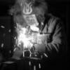
Stigian 1,234 #62 Posted February 21, 2018 Afternoon all, let's start this update with a milestone in the build... First start of the engine..... Of course it didn't go smoothly to start with.. Although the wiring was operational enough to get the engine running, for some reason I just could not get the two warning lights or the temp guage to work... These three! The one place where the lights/temp guage connect wiring wise is the voltage regulator which should (or so I thought) power the lights etc.. Now I will admit to to getting the power leads to the battery around the wrong way once, that coupled with finding out the regulator should be rubber mounted to the frame (so it doesn't earth through the frame) rather than bolted directly to the frame as I had done once! So... Everything pointed to a fried regulator being the problem, a replacement with correct mounting bracket with the rubber bits was ordered.. The result??? No Change! The problem is this black wire from the regulator, there should be power in it but it was missing! Time for a coffee and a bit of research on the internet to find out exactly what the blasted black wire does.. As it turned out it's the wire the regulator uses to keep a check on the voltage and should be connected to a live.. At the front-ish of the loom is this connector that has been taped up as I thought it wasn't needed... Yes it's the other end of the black wire and it should of been connected to a live feed form the ignition switch! "Bangs head and has one of those Doooohhhhhh moments"! With that black wire connected to a live this was the result I know that in the grand scheme of things a couple of warning lights isn't a big deal, but it was really bugging me as to why they were not working! 1 Share this post Link to post Share on other sites
Stigian 1,234 #63 Posted February 21, 2018 With the wiring (mostly) sorted I couldn't tidy the loom up without knowing where all the wires would run to... All of which means I had to find somewhere to mount the battery! The only place for it to go was just infront of the rear R/S wheel (no pics as it's hard to hold a battery in place and take photo's at the same time), no ideal but it just would not fit anywhere else! I had already built a battery box, but hope to mount it??? This TB mount looks a good start Lot's of chopping and welding later it looked like this Inside view. Outside view. Checking the battery box fits.. TB/Batt mount bolted back on to MadTrax Battery plonked in place.. It feels nice and strong with no movement and will hold the battery in place no problem Share this post Link to post Share on other sites
Stigian 1,234 #64 Posted February 21, 2018 Now, back to the wiring... This isn't what's left of the loom, it's all the bit's I didn't need mostly chopped from wires that were too long! As I went along all the crimp connectors were removed and the joints soldered up before being wrapped in tape.. At least I know the loom won't pull apart now Battery end of things. This bit of the loom was a massive mess with lots of crimp connectors! It looks way better now The front end splits nicely into two, it will split nicely into three when the headlamp is wired in.. Speaking of the headlamp, these "not yet connected" wires go to the Quadzilla switch gear and are the very wires that give life to the lighting circuit. And the horn Monday was spent turning this mess.... Into this non mess...... A day well spent Having already mounted the voltage regulator the wrong way ie bolted directly to the frame, I needed to find a good way of rubber mounting it.. Which is where the random bit of Quadzilla comes into play as it has a few holes already with rubber isolating mounts in it... Just not quite in the right places..... Soooooo.. Chop of the unwanted bits. Slice 4mm from the middle. Weld the two halfs back together. That should be strong enough Drill a hole. Bash the bend flat. Drill a second hole then test fit. Cut and grind the bracket to shape. Bolt the regulator back on to the bracket. Bolt the whole thing back on to MadTrax, plug the wires in.... Job done 1 Share this post Link to post Share on other sites
elcamino/wheelhorse 9,054 #65 Posted February 21, 2018 When this project is complete perhaps you should ride it to get the metal from the scrap pile. The ride may not be good for the knees , but it would be fun. 1 1 Share this post Link to post Share on other sites
CountryRock 198 #66 Posted April 11, 2018 Any updates? Quite the project you've made out of this. Interested to see it come alive again. 1 Share this post Link to post Share on other sites
Stigian 1,234 #67 Posted May 16, 2018 On 21/02/2018 at 10:06 PM, elcamino/wheelhorse said: When this project is complete perhaps you should ride it to get the metal from the scrap pile. The ride may not be good for the knees , but it would be fun. Hi Jim, I can see a few scrap pile trips coming up on MadTrax, a tow ball will be going on the back, ideal for a small trailer On 11/04/2018 at 4:45 PM, CountryRock said: Any updates? Quite the project you've made out of this. Interested to see it come alive again. Hi CountryRock, there is quite a big update to come so watch this space.. "Quite a project" might be a tad of an understatement... It's what happens when you get carried away and things evolve Hi all, sorry for the total lack of updates of late. I knew I was a bit behind but didn't realise Feb 21st was my last posting! I'd best get on with an update.. While digging through the Quadzilla wiring loom for connectors to pilage I found something that would most certainly be a good upgrade.. So this small bracket was made.. It was welded onto the frame just under the seat. If you hadn't guessed it holds up a modern fuse block, much better than the old Honda one With the 4 wheel drive bit wired in, the time had come to think about lights starting with the er.. headlamp.. Not having the correct bulb holder (which would of been for a really old style bulb anyway) I had this problem to overcome! I had an idea on how to solve the er..gap problem but not the materials until Nigel found me this old pully.. Thank Nigel No photo's of all the lathe stages (plenty of that in the next video) but the pulley ending up looking like this.. The shallow slots were done with a milling bit in my pillar drill. Not ideal as the bed does try to move sideways! The bulb pokes through like this. Then the whole thing drops into the back of the lamp bowl. The little black slot through the bowl is a handy bolt hole, as is the one the other side Now something to hold the bulb to the holder. Starting with this.. Thanks again Nigel It was turned into this.. Which of course fits here.. I found some nice small bolts to use but I didn't have a tap to cut a thread..... So I made one Best test it.. Yep it works... Lots of drilling, thread cutting and countersinking and bolt shortening later.. Tad-Daaa A lot of work for something that won't be seen 2 Share this post Link to post Share on other sites
Stigian 1,234 #68 Posted May 16, 2018 It's video time.. Lot's of timelapse bits Share this post Link to post Share on other sites
Stigian 1,234 #69 Posted May 16, 2018 Back to the headlamp but only very quickly.. When it came to wire the lamp in I found there wasn't enough space around the outside of the bulb holder to run the wires,so three holes were dilled and then slotted to feed the wires through. Time to turn to the other end of MadTrax.. Starting with a cardboard template.. Which fits about here.. I'm sure you will of guessed by now it's for a rear light.. Even though I've no plans to put MadTrax on the road it needs a rear light to balance out the front light.. Not having any rear lights that will fit I need to make my own, starting with this Honda Silverwing light lens. Trimmed to shape including the lens inside. Hard to hold in position and take a picture! I have an idea on how I want the rear light to look, template time.. Rubbing dirty fingers on paper to make some marks and then cutting out didn't work too well.. No idea why this pic keeps turning around! Template number 2 involved cutting lots of bits of cardboard but it looks much better and is much more usable as an actual template Turning this into steel is going to be fun The transfer box gear stick needed a tweak so it wasn't in the way of any knees, so it was moved in by an inch, lengthened and a new hip and groovy knob was put on the end It needs a little tidy up but it looks good Back to the rear light and I needed some sheet steel to make it from. This will do.. Yes it came from our old tumble drier and still has some fluff on it to prove it A grinder with a 1mm disc was used to cut the long slices, a sharpened screwdriver (yes it was a very old one of which I have many) was used to chop the ends out. No idea why certain photo's like to turn the wrong way! Lot's of time spent with a file later and the lens almost fits. Time to bend the edges round, wanting a nice curve some bar stock was used for beating around. Ta-Daa. A lens check. "Let there be light" And held in postion. 1 Share this post Link to post Share on other sites
Stigian 1,234 #70 Posted May 16, 2018 It was at this point my hands were not too happy about beating and shaping metal, so I thought I do something less hand straining on the lathe.. This UJ was part of the drive system when I thought lot's of UJ's were a good idea! The problem is I had also welded a splined bit inside one end, and the said splined bit fit's the splined shaft that comes out the bike gearbox! It's a shame to chop a UJ up, but when needs must.. Here's what's left of the UJ on the lathe having just broken through one end so I can get to the splined bit. The hidden splines.. Knocked out with a hammer and drift. All that work for this little bit of steel slid on the gearbox shaft! Time to think about mounting this large lump of 90'd drive! This 10mm thick steel plate should be strong enough Lot's of lathe and drill action later... (all the action coming up in the next video). Bolted on.. 1 Share this post Link to post Share on other sites
Stigian 1,234 #71 Posted May 16, 2018 It was at this point I started to have a few of those "Groundhog day" sort of moments! Having worked out how to make a shaft that fit's over the gearbox splines, has a bearing at the other end and also has a sproket in the middle, I proceeded to make a mess of things 3 times! Attempt 1... Having just checked the bearing fit I forgot to tighten the tailstock back up for the final cut! The result was some nice deep gouges! (not seen in this pic as I trimmed some more off to check which tools cut best) Attempt 2... Counted twice what I should of done and took too much metal off making the bearing a loose fit! Attempt 3!!! All was going well until I broke a small drill bit off about 1/2 inch in!! No way of getting it out! Attempt 4... In it's raw state And attempt 4 in it's finished (and correctly sized) state. Not a perfect finish inside, but the measurements are right. The splined bit pressure fitted, a nice tight fit.. It will be welded on then the welds and overhang will be tidied up on the lathe. And finally with the bearing, I still need to buy the sprockets but as they will need boring out to fit the shaft I could get on and make this part.. Plenty more lathe work to go, I needed to make something that would fit over this stepped shaft on the TB input side of things. The reason being I need to fit a sprocket to the shaft but there isn't a keyway for location, only splines at the outer end. Lot of time was spent with some 40mm bar to create this. Outer splines presure fitted to the sleave one end, it will be welded also. Stepped inside to fit the shaft. It would of been nice to cut a taper inside to match taper on the shaft, but don't have the tools to do it.. Splined sleeve bolted on the TB shaft, the sleeve walls are not thick enough to cut a keyway so the sprocket will have to be welded on. Back to the 90'd drive thingy from the Honda Silverwing that I'm using to turn the drive around.. On the bike the rear wheel would of bolted to this bit. But I need to put the drive from the gearbox into the 90'd drive from this way... But how to bolt a sprocket to it? Starting with a slab of 10mm thick steel and a photo that won't turn the right way! To bolt the splined bit flush on the plate I had to cut a wide groove in one face. That looks good. To fit a sprocket to all this a shaft is needed.. This will do. It fits in the circular plate like this, the tapers will be filled with weld. The other side will get welded on and the welds turned down to look good on the lathe.. The shaft has been made over sized as I don't know the measurements until I get the sprockets and try to fit the whole thing in place. This is quite a big "whole thing" to fit! 1 Share this post Link to post Share on other sites
Stigian 1,234 #72 Posted May 16, 2018 Nows a good point to drop in the next video.. enjoy Share this post Link to post Share on other sites
Stigian 1,234 #73 Posted May 16, 2018 As I didn't have the sprockets at the time, and most of the jobs left to do involve having the 90'd drive in place, I was scratching around for something to do on MadTrax, so I decided to sort this little problem out! The problem being it should fit here (the tape is only to keep the dust etc out), but I don't have a key for it! But I do have this tank from a Honda CX trike with a locking cap... I feel a bit of tank slicing coming up It would of been a shame to scrap the fantasic art work... So I now have some more wall decoration The filler hole section was cut from the CX tank, cleaned up and tried for size on MadTrax's tank. To mark where I would need to cut on MT's tank I needed to cut out a small section so the new bit would sit flat.. And here is the very same hole after being part welded back in! Yes my brain wasn't functioning to well that day and I cut too much out! The correct size hole marked and cut out.. A test fit, only a few little tweaks needed.. While I was getting on with the welding Rob was cleaning all the paint off the locking cap thingy. Quite a few layers of paint! Ta-Daa As you can see with the flap open it needs a little bit of filler work.. Not much though I gave it a quick coat of paint to help show up where I may of missed any welding... Here's one of the holes. The new cap looks the part, I can't decide if it needs painting of just a coat of matt clear coat.. Time will tell 1 Share this post Link to post Share on other sites
Stigian 1,234 #74 Posted May 16, 2018 Still no sprockets, so I thought I'd continue with the rear light.. Starting with this not quite flat steel sheet. By not quite flat I mean the sheet has had a big cross pattern pressed into it which I though would be good for the back of the light box.. Marked out ready for cutting. Lot's of chopping, welding and weld dressing later I had this. The cut out at the base is so the box can fit over the anit roll bar tube. These are the buld holders I will be using.. This ally plate is the right thickness to hold the er.. holders nice and tight, so five holes and a bit of cleaning up later.. To mount the bulb holder plate to the inside of the light box but leave enough space behind for wiring etc I made one of these.. Captive nuts welded on the back. A quick bulb test fit. Curved panel made to fit the anti roll bar hole.. But before it was welded on the bulb holder plate was plug welded in.. Checking the bulb holder still fit.. They do A view inside. Lot's of welding and weld dressing to do.. That looks better Best check it still fit's MadTrax!! It does Some of the welds down the sides needed a few extra blobs of weld to tidy them up.. The front edges needed a bead of weld to fuse metal together.. To make life easier I clamped on a flat brass bar to weld against as welds will not stick to the brass.. As you will of noticed on the above photo the longest which is also the top panel is a little on the wonky side.. A big thank you to Rob for the square which came in handy for showing how wonky wonky is.. As the metal is too stretched to hammer flat some extra straight strength needs to be added.. Starting with a strip of double skinned steel. Most of one skin was cut away leaving only a small rolled edge sort of thing. A quick trip to the sheet metal folder which I should use more than I do! Plug welded inside.. The bit of black box section is only to make sure everything clamps down flat.. Can you spot a slight problem here? Yep, the box is such a good tight fit it won't come back out again! The next step was to make some mounts for the rear light, but a parcel turned up containing these sprockets The rear light is going to have to wait, getting the drive train finally finished needs to come first.. Soooooo, the first sprocket on the lathe being bored out to a larger ID.. 1 Share this post Link to post Share on other sites
Stigian 1,234 #75 Posted May 16, 2018 Video time again Share this post Link to post Share on other sites