callum12 257 #1 Posted June 20, 2015 Hi all,I have got a clevis hitch for Agri-800 but I'm a little confused as to how it it s moved via the deck lifting arm. could anyone give any pictures of how it is all connected with the rocker shaft and so on? i will be making it completely mechanical. thank you very much callum Share this post Link to post Share on other sites
6wheeler 676 #2 Posted June 20, 2015 I can't get pics for ya. But, the parts you need are of course the hitch itself. Then, the rock shaft which connects via an adjustable chain to the hitch (this would be located under the seat/fender pan). Then you need the lift cable. This cable has a clevis on one end and an adjustable trunion on the other end. It goes through the existing tube on the top left of the rear axle (looking at it from the rear). The clevis end hooks up in one of the holes on the deck lift arm under the tractor ( the hitch lifts the same as the deck does). And, lastly the trunion hooks to the rock shaft. Hope this helps. Pat Share this post Link to post Share on other sites
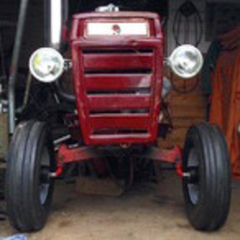
Ed Kennell 46,609 #3 Posted June 21, 2015 Does this help? 2 Share this post Link to post Share on other sites
callum12 257 #5 Posted June 21, 2015 thanks everyone, yes the pictures have helped a lot, do you have a picture of the whole rocker arm, the tube part and if possible the adjustable trunion?i have got the actual hitch and i brought a caravan breakaway cable but i reckon it might be a tad thin. the hitch is for my modified A-800 so i am making the hitch system from scratch, I'm just seeing how it is done rather than faffing around reinventing the wheel! Callum Share this post Link to post Share on other sites
meadowfield 3,080 #6 Posted June 21, 2015 try here for some ideas http://www.wheelhorseforum.com/topic/53389-diy-clevis-hitch-lift/#comment-495904heres one I made earlier... Share this post Link to post Share on other sites
callum12 257 #7 Posted June 21, 2015 there's an idea , you just wanted to show off didn't you! hahai reckon i will steal you're rocker shaft idea, I've got two 15mm pillow block bearings from my A level engineering project that weren't used. i could use those mounted on some angle iron then to the chassis. flange bearing would be easier but i might as well use what I've got ( considering I've just spent £300 on an angle drive! )what I've found after mocking up the lift system is that there is only just enough range of movement, ideally i would like there to be a few inches more. this is easily achieved with the rocker shaft but it would mean i would have less mechanical advantage over the hitch and implement. after mounting one of my implement i found that is is easily lifted but i reckon a plough where the weight is much further back could be quite difficult. how difficult is it to lift the plough? and from fully lowered to highest position how much does the hitch raise? thanks all,Callum Share this post Link to post Share on other sites
callum12 257 #8 Posted June 22, 2015 decided against using the pillow blocks, not worth it really not to mention they might foul the brake assembly if it is ever adjusted (which it will). so i made some 10mm thick flange things that are bolted to the chassis and the 15mm bar runs though those with the rocker shaft welded to that. I'm going to do it so there is plenty of adjustment, by making the position of the wire from the lift handle i can adjust how much mechanical advantage i have over the implement and the amount the hitch moves up and down by. By making the position of the chain adjustable i can adjust the 'fully down' height of the hitch. i'll post some pics over on 'Agri-800' tomorrow.thanks for all your help,Callum Share this post Link to post Share on other sites