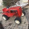
mikeeyre74 290 #1 Posted April 20, 2015 I bought this 36" mower deck from a guy on CL, and he brought up the missing parts that my mid mount plates didn't appear to have. But I can't for the life of me figure out how this is supposed to go together. But maybe thats because I have the wrong stuff? There's no identifiers on the deck, so I can't find a manual for it.. It's a 36" read discharge model. Can you take a look at these pieces and tell me if I even have the right mid mount parts? It's supposed to be going on a '77 B-80. Share this post Link to post Share on other sites
gwest_ca-(File Mod) 12,370 #2 Posted April 20, 2015 See if this helps. The round disc ends up on the left side and on the front of the hitch. Do you have the spring? Left and right is always from the operator's position. Garry 1 Share this post Link to post Share on other sites
Lane Ranger 12,031 #3 Posted April 20, 2015 (edited) The two pieces in the second photo ride in between the two plates on the frame (they are bolted on and you can remove one side to slide the two pieces in the second photo on) small rod goes in small hole and larger locking piece will close around the front 3/4 bar on your 36 inch mower deck lift frame. The front bar will ride between the two bigger bands of steel riding on the front bar (look closely. You slide the mower deck in from the right side of the tractor (from the back looking forward) with front wheels turned to far left. Slide the inner bar with holes into the lift bar rod that hangs down from the B-80 lift. That should get you in position to then place the front mower deck bar up into the attach-a-matic . I usually go to the left side of the tractor to operate the attach-a-matic and have someone on the opposite side left the bar at the same time to propery place and lock it with the attach-a-matic. You just need a spring that will give enough tension to open and close the rod on the attach-a-matic so the locking mechanism works if you do not have one. Any good hardware will sell you one just take the rod in to fit the spring. I think there is a little e ring on the end that is suppose to hold the spring in place also. Edited April 20, 2015 by Lane Ranger Share this post Link to post Share on other sites
gwest_ca-(File Mod) 12,370 #4 Posted April 20, 2015 These pages on a mower deck may help also The hooks on the hitch hang down. The round disc prevents the hooks from opening. Push the disc in against spring pressure and this allows the hooks to swing forward past the disc and the mower cross shaft can drop out. Garry Share this post Link to post Share on other sites
mikeeyre74 290 #5 Posted April 21, 2015 While all this makes sense, it just doesn't seem to work. I took another photo with the parts installed like you're advising, and well, here: Whoops! So, anyway, the wheel/disc thing seems to be such a large diameter, that it won't slide in behind that locking mechanism there to hold the deck in place. It seems like I've got the wrong parts, no? Share this post Link to post Share on other sites
Shuboxlover 488 #6 Posted April 21, 2015 I think that piece it for a GT-14, but I'm not 100% sure. I have a nice mid attach assembly I'd sell for reasonable. PM if you're interested Share this post Link to post Share on other sites
gwest_ca-(File Mod) 12,370 #7 Posted April 21, 2015 See your problem now. Didn't realize there are different ones for that width of frame. Garry Share this post Link to post Share on other sites
mikeeyre74 290 #8 Posted April 21, 2015 The side plates that bolt to the frame were on the machine.. You think it's just the lock mechanism that I got separately that's the problem/wrong piece? Share this post Link to post Share on other sites
Don1977 606 #9 Posted April 21, 2015 The spring latch and wheel is right. I just look up in the parts. That latch plate looks like a 71 model from a "speed hitch" that just used a spring clip to hold it closed. Share this post Link to post Share on other sites
mikeeyre74 290 #10 Posted April 21, 2015 I think you might be on to something there.. Share this post Link to post Share on other sites
gwest_ca-(File Mod) 12,370 #11 Posted April 21, 2015 Measured the holes in the side plates you are using. The B-80 and C-120 use the same parts. 1977 C-120 8-Speed the holes are 1-11/16" center to center 1990 312-8 the holes are closer to 1-3/4" center to center Both models use the same disc and side plates so the dimensions should be the same. The latch is different on the 312-8 because they extended the rod on the latch to form a handle outside the plate. Gives you something to compare Garry Share this post Link to post Share on other sites