Jump to content
Sign in to follow this  
stephan07

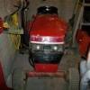
re wiring the engine from my 86 310

Recommended Posts

stephan07

i have been trying to rewire my 310 (all the wiring had been removed) and have been able to get it to start and run with no problems but i am on the charging system and from my wiring diagram i have figured all but one wire i think. the wire in question is the 3rd wire in the connector from the charging system can any one tell me what it is for? the other two should be my charge and lights.

Share this post


Link to post
Share on other sites
 
Save Old Iron

Have you determined if the stator in your engine is the 3 amp or the 15 amp stator?

Physically, they are completely different in appearance. Identification of the stator capacity should not have been a problem.

If you do not remember what stator is present on your engine, a multimeter can be used to measure the resistance to ground thru either of the charge wires, 15 amp stators will not show resistance to ground.

3 amp stators will show resistance to ground on the charge wire and the lighting wire.

Share this post


Link to post
Share on other sites
 
stephan07

3amp i am pretty sure

Share this post


Link to post
Share on other sites
 
Save Old Iron

I don't own a tractor with a 3 amp system but the ones I have worked on, only two wires are connected to the stator.

http://www.smallengi..._coil17053.html

One for lights, one for charge.

What color is the other wire on your setup? Where does it lead to?

I'm sure there may be other style stators which have 3 wires? Unless the third wire is the kill wire used in magneto based systems.

Share this post


Link to post
Share on other sites
 
stephan07

so i pulled the sheet metal off the engine and the wire is just broken off back there doesn't go to the stator

Share this post


Link to post
Share on other sites
 
Save Old Iron

OK, a broken wire. What color ?

Does the engine shut off using the ignition key? this would suggest you have the magneto kill wire connected correctly.

The other two wires should be a black and a yellow ?? Black should be the battery charge wire and yellow should be the power to the lights.

Does the black wire from the stator have a "lump" in the wire. That lump would be the diode that signifies the wire functions as the battery charger.

Share this post


Link to post
Share on other sites
 
stephan07

m9qqRTYRzrx-YVMJaMwZ9sA.jpg

this one pictured is the same setup as mine the third wire appears to be black on both mine and in this pic. so i have two blacks and a yellow.

Share this post


Link to post
Share on other sites
 
TT

Is your 310 an '85 or '86 with a K-241 Kohler?

In the picture you posted above, the third wire with the ring terminal should be ignition coil +

Share this post


Link to post
Share on other sites
 
Save Old Iron

there should be two yellow wires beginning at the stator and heading into a protective sheath - one of the yellow wires will be soldered to a diode "lump" at the opposite end of the protective sheath - the diode should come out of the sheath as a black wire which would be the battery charge connection.

3ampStatoroutputs_zps804859da.gif

the other yellow wire emerging from the sheath is for the AC voltage to the headlights.

the third free hanging wire probably is the ignition coil wire as TT says - but you said you have the tractor running - so you may not need that one in the harness. maybe that is why it is cut / broken off ?

Let us know if this is a K or Magnum engine. Thanks

Share this post


Link to post
Share on other sites
 
stephan07

it a k241 and it is a 86. it was used as a pulling tractor and the p/o took the engine and wiring but did include the oe engine

Share this post


Link to post
Share on other sites
 
Save Old Iron

the yellow wire from the stator can be run to one leg of an SPST "LIGHTS" switch on the dash. The other leg of the switch goes directly to the lights wiring. When you throw the switch, the current from the yellow wire goes thru the switch to the lights, simple enough.

The black lead with the diode can be wired directly to the "R" terminal of the ignition switch. When the igntion switch is in the RUN position, the stator wil deliver minimal charge current to the battery thru the ignition switch.

I assume you have the ignition circuit wired to your satisfaction, so ignore (cut off ?) the 2nd black wire on the stator connector.

Share this post


Link to post
Share on other sites
 
Save Old Iron

If you can, it would be of help for future reference to others if we were able to identify the positions of each wire in the connector. If you have a picture of the connector and wiring, great. If not, just call out what wires are present at the differenct connector positions seen in the above picture. For visual reference, let us know the wire color going to the 11 o'clock, 2 o'clock and 5 o'clock positions (as seen in the above picture).

Thanks

Share this post


Link to post
Share on other sites
 

Create an account or sign in to comment

You need to be a member in order to leave a comment

Create an account

Sign up for a new account in our community. It's easy!

Register a new account

Sign in

Already have an account? Sign in here.

Sign In Now
Sign in to follow this  

×
×
  • Create New...