Sign in to follow this
Followers
0
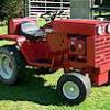
D-200 Automatic restoration
By
wheeledhorseman, in Wheel Horse Tractors

By
wheeledhorseman, in Wheel Horse Tractors