combatmp29r 27 #26 Posted March 26, 2008 Greg, yes I do. I was looking at how weak that edge was today when I took the pics. I have a piece of 1/8" x 1/2" flat stock that I'm going to weld at a 90deg angle to the top edge. that should stiffen it right up. The first one I built with an old bolens blade and it had the curved angle iron supports like the WH front blades have. I just welded andgle between them on it. :thumbs: Share this post Link to post Share on other sites
T-Mo-(Moderator) 4,889 #27 Posted March 26, 2008 Joel, Looking nice. I think adding gussets to the blade mount is a very good idea. And adding reinforcement to the blade is good idea also. On the 1" bolt diameter, the shank on a 1" bolt has a major diameter of over 1 inch and it depends on the thread size, i.e. UNC or UNF or ACME thread or NPT, etc. It's good to have a design hand book at your disposal at work. :thumbs: Share this post Link to post Share on other sites
wse100 0 #28 Posted March 26, 2008 combat, That blade looks great, i see you you made a "clean cut" cutting the blade in half...did you use a plasma cutter? I love the plasma...So clean & not molten hot. :thumbs: Share this post Link to post Share on other sites
Greg B. 1 #29 Posted March 26, 2008 Here's one for the engineering types, in here. For the type of blade illustrated in this thread, what is the optimal, fore and aft, location of the cutting edge? Should it be centered on the wheelbase or closer to the rear wheels? It's difficlt to tell just from Photos. Greg B. Share this post Link to post Share on other sites
WheelHorse_of_course 101 #30 Posted March 26, 2008 From a grading/geometry perspective you want the cutting edge half-way between the center line (from axle to ground) of the two sets of wheels. The single biggest advantage of a mid-mount grader blade is that you automatically flatten the peaks and fill the valleys. This assumes of course you goal is to level! That said, a couple of inches either way doesn't seem likely to make a difference. Nice work :thumbs: Share this post Link to post Share on other sites
Greg B. 1 #31 Posted March 26, 2008 WHoc, Thanks. That's what common sense would dictate, but I've spent enough time in R&D to know that human logic can be wrong..... Greg B. Share this post Link to post Share on other sites
TT-(Moderator) 1,170 #32 Posted March 26, 2008 Here's one for the engineering types, in here. For the type of blade illustrated in this thread, what is the optimal, fore and aft, location of the cutting edge? Should it be centered on the wheelbase or closer to the rear wheels? It's difficlt to tell just from Photos. Greg B. Greg, I built mine so when it was at full angle, the end of the blade had a few inches of clearance at the rear tire. Here's a LINK to my pictures of when I pulled mine apart so Joel would have something visual to work from. Share this post Link to post Share on other sites
combatmp29r 27 #33 Posted March 26, 2008 On the 1" bolt diameter, the shank on a 1" bolt has a major diameter of over 1 inch and it depends on the thread size, i.e. UNC or UNF or ACME thread or NPT, etc. It's good to have a design hand book at your disposal at work. JD where the H#$% were you when I bought the bolt?? I couldn't bring myself to spend $25 at TSC for a 3' piece of 1" round bar when I only needed 6". Bolt looked like a good choice at the time WSE100 Nope no plasma yet Next on the toy list though. This one was done by the old handy dandy sawzall and a box tube straightedge TT thanks for the extra pic backup. I meant to add that link with the dimension one at the beginning. My sometimers was qacting up that day I think :P Share this post Link to post Share on other sites
catman81056 3 #34 Posted March 26, 2008 Joel thats a nice looking blade, you're doing a super job starting from scratch. When I saw the pics of Terrys blade I thought it was an original WH blade. I think yours will be every bit as nice :thumbs: Share this post Link to post Share on other sites
Kelly 1,038 #35 Posted March 27, 2008 Looks very nice, alot cheaper than a WH grader blade even if you have to buy the 1" bar stock Share this post Link to post Share on other sites
combatmp29r 27 #36 Posted March 27, 2008 Thanks Tim and Kelly, Well tonight consisted of mostly honey do list stuff Gotta keep Nan happy though or no shop time I did however take about 1/2 hour and hillbilly machine the bolt down to work as the mounting pin. I started with the bench grinder and used to tool rest as a guide as I slowly turned the bolt and worked across the length like you would with a lathe. Then I sprayed the bolt with layout dye and hand filed it untill all the blue was gone and it had a uniform look to it. Works like a charm now Oh and note to self. Maybe lathe should go ahead of plasma cutter on the toy want list :thumbs: Share this post Link to post Share on other sites
T-Mo-(Moderator) 4,889 #37 Posted March 27, 2008 Sorry, Joel. I didn't know you were "sizing" one. Too bad I don't have another copy of my "Design Handbook" lying around. But there are some good ones, if not better ones, out there. :thumbs: Share this post Link to post Share on other sites
Greg B. 1 #38 Posted March 27, 2008 Thanks, TT Greg B. Share this post Link to post Share on other sites
perry 82 #39 Posted March 27, 2008 great job joel . first time i had a chance to look at your progress. i could always use another one also ............. :D Share this post Link to post Share on other sites
combatmp29r 27 #40 Posted March 28, 2008 I guess I'll let it slide this time Terry (JD) Thanks Perry. You know I just picked up a couple sears build your own blade kits No new progress today. I worked this morn, and Spent the afternoon at Gregs. Well afternoon/evening Yep probably sleeping with the horses tonight :P Share this post Link to post Share on other sites
Nick 13 #41 Posted March 28, 2008 Joel, The blade is looking good. Not much left now but to finish up and post those first test run pictures. I have not done a thing to my blade since I posted the pictures. Guess there are to many projects and not much progress. Nick in ohio Share this post Link to post Share on other sites
combatmp29r 27 #42 Posted March 29, 2008 Chapter 2 page.......................Uh oh yeah 3 I added a piece of 1/2x1/2x1/8" angle across the top of the blade for support. I also added the gussets to the blade mount. Now I just have to make the lift rod mounting block, the rod itself, and the angle adjustment lever. Should be done tomorrow :thumbs: Share this post Link to post Share on other sites
combatmp29r 27 #43 Posted March 30, 2008 Forgot to add these earlier, so chapter 2 page 3 foot notes Here is the machined blade mounting pin, and a couple pics of it on the V18 mock up chassis. That way Greg can see how the blade placement is. I'll try to get pics on a horizontal tomorrow. Share this post Link to post Share on other sites
Stigian 1,235 #44 Posted March 30, 2008 Nice work Joel, the blade looks much stronger with the added metal Cant wait to see the blade in action video :D Share this post Link to post Share on other sites
kj4kicks 154 #45 Posted March 30, 2008 Nice work Joel ! That looks much stronger than the OEM blades. Share this post Link to post Share on other sites
Greg B. 1 #46 Posted March 30, 2008 Good looking job, Joel, it looks a lot stronger and thanks for the side shot. Greg B. Share this post Link to post Share on other sites
Rollerman 291 #47 Posted March 30, 2008 Looks great Joel! Whats left the mechanism to lock it in at an angle & paint? Share this post Link to post Share on other sites
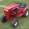
combatmp29r 27 #48 Posted March 30, 2008 Today was a rainy nasty day here so I spent it with the kids playing and watching Drag racing Tried to watch the nascar race but got vetoed for Dumbo Here are the horizontal pics on a C160 auto And after looking at the pics I had to go back out and look at the tractor (didn't look like it much room to lift the blade) With the front tires flat, rear tires low, and the front end up hill on the concrete the blade is actually about 2 1/2-3" up off level ground. Guess I should have got out the compressor and rolled the C back some first Tommorow should bring the lock lever and the first action photos I Hope Eldon , and Ian, yes it is heavier than a stock one, but I never seem to use anything exactly how it was intended anyhow Greg, your welcome, and I hope these pics help some too. Stephen, Yes that is all that is left to do. :D Share this post Link to post Share on other sites
Greg B. 1 #49 Posted March 30, 2008 Thanks again, Joel. There's no such thing as too much information. Greg B. Share this post Link to post Share on other sites
Kelly 1,038 #50 Posted March 31, 2008 Again very nice job, very pro. looking :thumbs: Share this post Link to post Share on other sites