Retired Wrencher 6,765 #1 Posted September 21, 2025 This is my first attempt at installing a solenoid. About installing one. my question in the third picture what goes there a ground wire and something else I think once I get those two 3/8 bolts that have a connection I think I can figure out the rest. Any help would be appreciated. If you have pictures, you can post them Share this post Link to post Share on other sites
WHX?? 57,273 #2 Posted September 21, 2025 Wire from s on the switch to the S on the solenoid. I terminal gets grounded. Should be nothing on the large terminals but power from battery and to starter. FYI the pigtail for that switch is readily available in the jungle and cheap. 2 1 Share this post Link to post Share on other sites
Retired Wrencher 6,765 #3 Posted September 21, 2025 5 minutes ago, WHX?? said: Wire from s on the switch to the S on the solenoid. I terminal gets grounded. Should be nothing on the large terminals but power from battery and to starter. FYI the pigtail for that switch is readily available in the jungle and cheap. Do you have a picture of your set up so I can clearly understand what we are talking about. Not good at wiring just need a clear direction pictures. Thank you. Share this post Link to post Share on other sites
WHX?? 57,273 #4 Posted September 21, 2025 5 minutes ago, WHX?? said: Should be nothing on the large terminals but power from battery and to starter. Well if take that back kinda... diagram shows it as a PTO off the battery side to power switch. Share this post Link to post Share on other sites
gwest_ca-(File Mod) 12,320 #5 Posted September 21, 2025 I believe the I terminal is not used. It is there to supply 12 volts to an ignition coil that uses a resistor to feed the coil. On starting the 12 volts from the I terminal provides a hotter spark. After starting the coil gets lower voltage from the coil through the resistor. In short it bypasses the normal ignition on startup only. If you ground the I terminal you will have a dead short when starting. No ground wire required with this solenoid as it is provided by it's mounting bolts. 1 2 Share this post Link to post Share on other sites
WHX?? 57,273 #6 Posted September 21, 2025 (edited) 9 minutes ago, Retired Wrencher said: Not good at wiring I can see that... I take wiring for granted as it's the only thing I'm decent at. If you was local I would gladly stop over and have it done in 10 minutes. I really enjoy it. The only pic I have showing that type of switch & pigtail. Edited September 21, 2025 by WHX?? Share this post Link to post Share on other sites
Retired Wrencher 6,765 #7 Posted September 21, 2025 26 minutes ago, WHX?? said: I can see that... I take wiring for granted as it's the only thing I'm decent at. If you was local I would gladly stop over and have it done in 10 minutes. I really enjoy it. The only pic I have showing that type of switch & pigtail. Do you have the solenoid connections in pictures? Share this post Link to post Share on other sites
Retired Wrencher 6,765 #8 Posted September 21, 2025 I have a 1056 I am putting this on. If you have pictures if the connections I would appreciate it. Share this post Link to post Share on other sites
WHX?? 57,273 #9 Posted September 21, 2025 (edited) No i don't have good pics. The only tractor I have a solenoid on is a 1067 and most of the wiring is concealed. Also I only use three term solenoids. Here is one from @Handy Don Note his fuse off the L reg terminal... not orginal but not a bad idea. A real hero would also put a fuse in the wire feeding the ignition switch as such on modern tractors. Edited September 21, 2025 by WHX?? 1 Share this post Link to post Share on other sites
squonk 47,244 #10 Posted September 21, 2025 Not all solenoids are the same. Some are grounded thru the mounting bolts and some through the 2nd small terminal. Let's ASSume you have a solenoid that is grounded at the mounts. At one large terminal you should have: Battery positive from the battery itself. Plus another wire with a fuse in it. This goes to the Bat terminal of the switch. On the 2nd large terminal, a cable to either a starter stud or the armature terminal of the genny. On the 1st small terminal you need a wire from the start terminal of the switch. You may need to try both small terminals to find out which one closes the solenoid when it get's 12 volts applied to it. If you have a solenoid that is grounded thru the 2nd small terminal, just ground that one. 2 1 Share this post Link to post Share on other sites
Handy Don 16,907 #11 Posted September 21, 2025 (edited) 2 hours ago, WHX?? said: A real hero would also put a fuse in the wire feeding the ignition switch as such on modern tractors. I did! It’s in the attached schematic but not visible in the picture. If it’d help, I can try to get some more images. With the tractor back together and fhe full tank in place it gets very crowded! Edited September 21, 2025 by Handy Don Share this post Link to post Share on other sites
squonk 47,244 #12 Posted September 21, 2025 (edited) In Jim's pic the large red is battery feed, the blue wire is to the bat terminal of the switch. The long small black wire is from the switch start terminal. The large black is to the Armature terminal of the genny and the small black wire on the 2nd small terminal is the ground. Edited September 21, 2025 by squonk 1 1 1 Share this post Link to post Share on other sites
953 nut 67,195 #13 Posted September 21, 2025 The solenoid you have pictured is a FORD unit which will work well. However, the "I" terminal should not have a wire connected to it. On Ford cars and trucks the "I" terminal bypasses the ignition resistor. Grounding is taken care of by bolting it to the engine. If you use a conventional garden tractor solenoid hook it up as shown below. Share this post Link to post Share on other sites
Racinbob 13,016 #14 Posted September 22, 2025 Do NOT ground the terminal marked 'I'. Just ignore it. Make sure the mounting bracket is well grounded. 2 Share this post Link to post Share on other sites
Retired Wrencher 6,765 #15 Posted September 22, 2025 13 hours ago, squonk said: Not all solenoids are the same. Some are grounded thru the mounting bolts and some through the 2nd small terminal. Let's ASSume you have a solenoid that is grounded at the mounts. At one large terminal you should have: Battery positive from the battery itself. Plus another wire with a fuse in it. This goes to the Bat terminal of the switch. On the 2nd large terminal, a cable to either a starter stud or the armature terminal of the genny. On the 1st small terminal you need a wire from the start terminal of the switch. You may need to try both small terminals to find out which one closes the solenoid when it get's 12 volts applied to it. If you have a solenoid that is grounded thru the 2nd small terminal, just ground that one. Thanks Mike for the info. Share this post Link to post Share on other sites
Retired Wrencher 6,765 #16 Posted September 22, 2025 Thanks everyone for the comments. I believe I got it in this old noggin of mine. Plenty of pictures of everybody’s comments. Should be a fun project. Enjoy your day. 1 Share this post Link to post Share on other sites
Retired Wrencher 6,765 #17 Posted September 22, 2025 (edited) 11 hours ago, 953 nut said: The solenoid you have pictured is a FORD unit which will work well. However, the "I" terminal should not have a wire connected to it. On Ford cars and trucks the "I" terminal bypasses the ignition resistor. Grounding is taken care of by bolting it to the engine. If you use a conventional garden tractor solenoid hook it up as shown below. Thank you :Racinbob: for the pick. I believe I have all the info I need to do this job now. Enjoy your day. And this time I will save it not throw it away way. I have done this before but it was a few years ago. I have a one minute memory. Edited September 22, 2025 by Retired Wrencher Share this post Link to post Share on other sites
Retired Wrencher 6,765 #18 Posted September 25, 2025 (edited) On 9/21/2025 at 6:57 PM, 953 nut said: The solenoid you have pictured is a FORD unit which will work well. However, the "I" terminal should not have a wire connected to it. On Ford cars and trucks the "I" terminal bypasses the ignition resistor. Grounding is taken care of by bolting it to the engine. If you use a conventional garden tractor solenoid hook it up as shown below. Hi Richard, in this picture below the 25 amp fuse goes from positive side of the battery to the lights or L on the voltage regulator? Edited September 25, 2025 by Retired Wrencher Share this post Link to post Share on other sites
953 nut 67,195 #19 Posted September 25, 2025 1 hour ago, Retired Wrencher said: Hi Richard, in this picture below the 25 amp fuse goes from positive side of the battery to the lights or L on the voltage regulator? The picture you attached was from @Handy Don, The fuse shown apparently would be from the "L" terminal of the voltage regulator to the lights if this is a four terminal regulator. Perhaps Don will join the thread and confirm this. Share this post Link to post Share on other sites
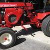
Handy Don 16,907 #20 Posted September 25, 2025 (edited) 6 hours ago, Retired Wrencher said: Hi Richard, in this picture below the 25 amp fuse goes from positive side of the battery to the lights or L on the voltage regulator? 5 hours ago, 953 nut said: The picture you attached was from @Handy Don, The fuse shown apparently would be from the "L" terminal of the voltage regulator to the lights if this is a four terminal regulator. Perhaps Don will join the thread and confirm this. Glad to. My apologies. In the setup pictured, I should have called out that this was an after-market regulator where the terminals were not in their usual places. They were (Left to Right): BAT, GEN, F. There was no L. (See * below for when/why L and BAT act differently.) The picture was really to respond to the solenoid mounting question in the thread! 😁 Since that shot was made, the aftermarket regulator failed (shocking!) but I was able to replace it with an “original” Delco, now installed, with terminals in the expected places and wired per the diagram in post #11. (And yes, this worker tractor needs a bath!) Sorry for the confusion! 😢 * Why are L and BAT different? Some regulators can gradually decrease the charging current deivered from the BAT terminal to prevent “cooking” a fully charged battery in hot weather. The L terminal always gets full voltage and current. The “don’t cook” regulators have three electromagnets inside. On regulators with only two electromagnets, L and BAT are electrically identical. Edited September 25, 2025 by Handy Don Share this post Link to post Share on other sites
Retired Wrencher 6,765 #21 Posted September 25, 2025 So does the POS side of the battery to the L on regulator? So in your opinion, is that correct? I have a Ford solenoid. Do I need to do this? I always buy things from Napa. Apparently that’s the one I carry in the old Ford style. Share this post Link to post Share on other sites
Handy Don 16,907 #22 Posted September 25, 2025 (edited) 2 hours ago, Retired Wrencher said: So does the POS side of the battery to the L on regulator? So in your opinion, is that correct? I have a Ford solenoid. Do I need to do this? I always buy things from Napa. Apparently that’s the one I carry in the old Ford style. The L terminal on the regulator, if present, is unused on a starter/generator 1056 tractor having no lights or other powered accessories (either with or without a solenoid) The BAT terminal on the regulator goes to the R (for Regulator) terminal on the ignition switch after passing through the ammeter and, ideally, a 15 amp fuse. Green and white in the diagram below. The B terminal on the ignition switch goes through a 15 amp fuse and then either: - directly to the POS battery terminal or - to the heavy terminal on the solenoid which is then connected to the POS battery terminal. Blue and black in the diagram below (and in post #11. So: - BAT to R supplies charging voltage into the ignition switch. - Ignition switch directs incoming charging voltage on R over to B while the switch is in RUN - B to POS battery terminal takes charging voltage out of the ignition switch and into the battery - L can also stand for lonely -- NOTHING connected! Edited September 25, 2025 by Handy Don 1 Share this post Link to post Share on other sites