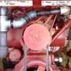
Trouty56 567 #1 Posted April 21, 2014 I have a 1984 C-145....wasn't charging.....It doesn't have a typical finned rectifier on it....has a little square jigger (I guess this is the rectifier/regulator) behind the battery....the wiring looked foriegn to me so I wired it the old way with an oldtime rectifier for now. Papaglide just acquired an 84 165 with the same setup. Any information on the correct wiring for this would be appreciated. Looks like only one leg of the AC heads in to the box and a thin wire out to the DC line.....not sure where the other AC leg goes. Looked for an 84 manual for the C's but they end on 83...for the blackhoods..... If you need any pics....can probably get you something tomorrow morning..... Share this post Link to post Share on other sites
gwest_ca-(File Mod) 12,015 #2 Posted April 21, 2014 Never noticed that before. The Wheel Horse part number for the regulator is 109313 and it shows up in this manual on page 11. This regulator was used on the single cylinder Kohler powered models 1982 8hp, 10hp, 12hp and 14hp 1983 8hp, 10hp, 12hp and 14hp 1984 10hp, 12hp, 14hp and 16hp Interest in knowing where the 2nd AC stator wire goes. That manual shows it going to the regulator but it may have gone to the DC+ output line as one AC terminal is common with the DC+ terminal on the finned regulators. Garry Share this post Link to post Share on other sites
red&green 1 #3 Posted April 10, 2015 (edited) C-145 square regulator-rectifier PN: 109313 Confusion occurs because of a problem with the diagram. Although it shows the connection to the regulator/rectifier, which would be correct for a 3-wire unit, it is missing the wiring layout of the connector itself as used on the 2-wire model. I have included a drawing of the 2-wire version with the missing segments added. According to another Wheel Horse wiring diagram, some production had black wires with color stripes for identification; my reference to the wire colors, BLK/red and BLK/wht, is from that diagram. A description of the circuit using conventional current flow, starting with the first half-cycle of alternating current produced by the Alternator: Coming from Stator terminal S2, current flows through the connector, follows the YEL wire loop on the regulator side of the connector, back through and out on both the BLK/red and BLK/wht wires. The BLK/red wire carries current to the Amp Meter, then to Battery +, Battery -, to ground. The BLK/wht wire carries current for all other electrical loads, which terminate to ground. Since the Regulator case is also grounded, the current, after being voltage regulated, follows the YEL lead to the connector, then to Stator terminal S1. The second half-cycle is reverse flow which is blocked by the rectifier portion (probably an SCR circuit for both voltage regulation and rectification). The small-gauge RED wire, from the connector to the Regulator/Rectifier, provides power for the internal electronics. This describes a half-wave rectified DC system. Edited April 10, 2015 by red&green 1 Share this post Link to post Share on other sites
bikingmike 0 #4 Posted May 17, 2017 From what I can see, the diagram here is the same as what I have always had. All that I see for a correction is the addition of, [corrected for 2-wire regulator -rectifier] and S1 and S2 on the rectifier/regulator. The rest is what my download showed and I figured it all out by just following the wires on the tractor. Share this post Link to post Share on other sites