Save Old Iron 1,563 #101 Posted October 30, 2012 Maybe SOI can come up with a recommended hook up with a relay so we can all add the loud horns to our twin ONANS 520s and 416s. It would be good if the test switch also tested the horn. 12V boat horns are really loud. Be happy to do up a circuit. We still need to come to some consensus as to what temperature to trigger the alarm at. The rest is really quite easy to implement. Share this post Link to post Share on other sites
nick9091 5 #102 Posted October 30, 2012 I have a 1995 416-H with about 430 hours. So far I have not had any engine problems. I have experienced grass,leaves and other debris getting sucked up on the engine fan screen. Getting tired of stopping to clean the screen, I came up with this solution. I purchased hardware screen at the home Depot 1/4 X 1/4 and fashioned a sort of half round screen from the bottom of the engine fan shroud from the front to the back also it covers about 3/4 of the height of the engine fan screen. Now when I cut grass the outer screen loads up with debris and the engine screen stays quite clean, since most of the debris comes from the cutting deck it collects on the hardware screen and clean air can still get to the engine fan from the open part of the hardware screen. I also have been reading theories about valve seat failures and broken rods. I have worked in Research and Engineering for Ford Motor Company for 35 years in Dynamometer engine testing, so I have some ideas about the failures. The cylinder temperature differences do not seem to be that big a difference to me. But here is what I know, carbon buidup in a cylinder will raise the compression ratio. Air cooled engines run hotter than liquid cooled engines, so air cooled eingines are more sensitive to fuel octane and spark detonation. If fuel octane is borderline sufficient with clean combustion chambers, when carbon buildup is present that will raise the octane requirements and cause spark detonation which in an air cooled engine may be hard to detect due to the fan noise and mower noise. Spark detonation will cause a very high tempertaure to occur in the cylinder and could be cause for the valve seat failures. I would suggest using non alcohol fuels in air cooled engines to get the highest octane possible as a means to avoid spark detonation. I am not sure what effect alcohol has on spark detonation but I know it's NOT GOOD for the fuel system gaskets, rubber and aluminum parts. One other observation on carbon buildup in the rear cylinder. We do not know what the fuel distribution is in the front and rear cylinders. You cannot asume that both cylinders are getting the same amount of mixture in the cylinders, in most engines that is not true. Usually one cylinder runs richer than the other, due to intake manifold and exhaust manifold flow. This difference in fuel distribution can be the cause of carbon buildup and it usually is the cause of temperature differences in cylinders. 4 Share this post Link to post Share on other sites
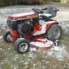
JackC 616 #103 Posted October 30, 2012 "This difference in fuel distribution can be the cause of carbon buildup and it usually is the cause of temperature differences in cylinders. nick, That suggests monitoring both cylinder temperatures and the difference can provide an early warning for carbon build up on one versus the other. "We still need to come to some consensus as to what temperature to trigger the alarm at. The rest is really quite easy to implement." SOI, The later 520H tractors already have an over temperature switch that will close when the switch threshold is exceeded. The switch just lights a small light bulb that is not very noticeable but I believe an audible alarm should also be incorporated. The low amperage audible alarms may be the easiest to add to those tractors. I do not know what temperature triggers the alarm. Also the triggering temperature may be different for different pick up points on the engine. I have a 1989 520HC and two 416Hs that do not have any over temperature sensors. I purchased a sensor and horn from a 724-Z that has the 24 hp ONAN. The sensor is normally open. I used a heat gun to heat it up to measure the temperature that closed the switch. I had to heat it up to over 500 degrees F to close the switch. While it was cooling down it opened at around 270 degrees F. Maybe 270 + say 30 degrees over or around 300 F degrees should be the number until we can get more data to confirm a number? The switch is used and while it works, I don't like the idea of waiting until the temperature exceeds 500 degrees F to trigger the alarm. The ideal device would allow the operator to set the trigger temperature. There are monitors that work that way and even allow the operator to bump it up in increments of 5 degrees on the fly for certain high demand applications. Below is a picture of the sensor switch and the test set up that I used. I did not have a helper to take pictures and I needed both hands one to hold the gun and one to hold the wires so I do not have pictures of the readings as they were measured. Maybe someone can remove the switch from their 520H and test it in a similar manner to compare readings. I know the 1996 and 1997 520Hs have them but the 1991 does not. I believe the sensor is attached to the bottom of the head of the rear cylinder. The newer 520Hs may use the same sensor that was used on the 724-Z. Share this post Link to post Share on other sites
JackC 616 #104 Posted October 30, 2012 I did notice some numbers stamped on the sensor. I see 309 over 0559. That may indicate 309 Celsius and 559 Fahrenheit which is close to what I measured. Technically 309C = 588F If that is what the stamped numbers mean then 559 degrees F would trigger the over temperature alarm. That seems way too high. Share this post Link to post Share on other sites
sorekiwi 761 #105 Posted October 31, 2012 From the "Demystification manual": The contacts inside the switch are normally open. As the body of the switch warms, the clearance between the contacts narrows, until the switch closes at 320-340 degrees F. It does not reopen until the temperature falls to 280-310 degrees F. Share this post Link to post Share on other sites
JackC 616 #106 Posted October 31, 2012 Good input, I did not think to check the Demystification manual. If anyone has the over temperature switch on their tractor they may want to take it off and verify that it closes at 320-340. I will have to retest the switch I have. Maybe I need to bring the temperature up slower. Mine did reopen at about the right point at 270 degrees. 1 Share this post Link to post Share on other sites
Save Old Iron 1,563 #107 Posted November 28, 2012 Jack, here is a first draft of the LCD readout for the Onan head temp monitor. I couldn't resist grabbing a few 16 character x 2 line displays with the selector switches (under the display). These 6 push button switches can be programmed to display any information you choose or toggle between different screens of info. I chose to default to a display of front / rear head differential temperature ( the 21 you see on the display). The display would indicate a 21 degree F difference between the head sensors and the ® indicates the ®ear head is 21 degrees hotter than the front head. If the front head where hotter, the ® will change to (F) for front. Pressing the "left" selector button will change the display to read both current and maximum temperatures of the REAR cylinder head. 296 is the current head temp and 378 is the maximum temp seen on the rear head since the tractor was started. Pressing the "down" button displays the lowest temperature seen on either head since the tractor was started. In this case, the (F)ront head temp was 75 degrees when the tractor was started and the (F)ront head temp was lower than the ®ear head temp at the time the recording started. When the "up" button is pressed, the maximum temp recorded on either head will be displayed. In this case the max temp was 346 degrees F on the ®ear head. Pressing the "right" push button displays the current and maximum temperature seen on the front head. Current temp is 275. and the maximum seen on the front head was 347 F. I still have to play with the text formatting as I find the use of the "F" in "Cyl Head Temp F" to be a little confusing when ® and (F) designators are used to display front and rear temps. So I'll play with it a little while I wait for the 4 line displays to be delivered. Since we have 6 push buttons on the screen, menus can be created to allow complete customization of the readouts (select F or C for temp display, etc). Any suggestions for display formats are welcome. 2 Share this post Link to post Share on other sites
JackC 616 #108 Posted November 29, 2012 I have some suggestions and created a jpeg file to display them. However, I get the message: "You have exceeded your allotted disk space for attachments" even before attempting to attach it. Any suggestions? Share this post Link to post Share on other sites
sorekiwi 761 #109 Posted November 29, 2012 That is awesome Chuck! Share this post Link to post Share on other sites
Save Old Iron 1,563 #110 Posted November 29, 2012 @ Jack - PM sent - and remember, other display formats are available. I'm waiting for the 20 character x 4 line displays to arrive. Hopefully they will be the black text on a light yellow background (which should be more readable in direct sunlight). Thanks Mike, but this is the easy part. All the displays and alarm trip points are just a matter of deciding how you wish to display the info and where to set off the alarms. Getting the proper style thermocouples and mounting them in the correct area of the cylinder heads - that will be the tricky part. I just received a few thermocouples that look promising. One is a 6mm threaded sensor with a 12.86 mm sensor depth (tip to bottom of nut). Hopefully a suitable spot can be found on the 520's cylinder head to mount these. More to come. Share this post Link to post Share on other sites
JackC 616 #111 Posted November 29, 2012 Chuck, email sent. Jack Share this post Link to post Share on other sites
Save Old Iron 1,563 #112 Posted November 30, 2012 Jack, I received your email and uploaded the formatting jpg you sent. I agree with your statement on putting the "Cylinder Head Temperature Monitor" logo on the enclosure and not consume "real estate" on the display itself. Of course this brings up the question on what style diplay case you have in mind for the final product. Will it be a "hide away" case tucked somewhere in the tractor and just log results or will the intent be to mount the display somewhere on the tractor always visible to the operator. My thoughts, especially for the 520, would be to delete the LED display currently at the top of the dash, implant 1 or 2 digital displays in the same area and use the LCD displays to report current status indicators for PTO, Brake, etc and a possible second display for additional custom indications like trans temp, head temp, etc. Share this post Link to post Share on other sites
Keith 21 #113 Posted November 30, 2012 I would just about bet you would find a bad valve guide in that cool cylinder. It would be interesting to see the EGT on that engine. I think valve guide wear is the critical factor. Once a year or two remove the head and clean the carbon and check valve guide wear. I think Onan specifies that the valves be checked periodically. Most air cooled motors need this maintenance but rarely get it. I also like the BMW boxers, beautiful motors. Share this post Link to post Share on other sites
Save Old Iron 1,563 #114 Posted November 30, 2012 Jack - rev 2 of the display as you requested Here's the logic so far. The default display will show both front and rear temps A suggestion I have is to delete the "delta" display and incorporate a delta reading on the main display. My suggestion is seen below with a 30 degree delta displayed. The software could be setup to display this delta reading only if it exceeds a certain trip point - say if a difference of 30 degrees or more exists. If the delta is less than your set point and of no immediate concern, no delta reading will be seen. Make sense? I also consider it important to know if the delta is increasing or decreasing as I watch the display. I could incorporate a "<" decreasing delta indication or an ">" increasing delta indication after the delta readout. Comments ??? Share this post Link to post Share on other sites
JackC 616 #115 Posted November 30, 2012 I like the way you have the delta displayed. There is a lot of good temperature information there with minimal display characters. I would always display the delta next to the hottest side as you have in the example. If it is always displayed the user can watch it change over time to warn of some condition that may be developing and the user does not need to decide on a threshold to set and can use the information as desired, I like always having that information visible and not hidden although the user can hide the display if desired. I think such a device is just as important for the 416s as the 520s, and maybe even more so. If I see temperature rising I may want to take action before a limit is reached. Grass collecting on the flywheel screen may cause temperature to rise and should be removed before limits are reached. I would keep the device somewhat generic in the beginning so that it can be used on many different tractors. It could be attached where the user wants it with a double sided tape. I like the idea of replacing the 520 upper dash but that is specific to the 520 and would take this to a higher level and cost point. If I had to pick one parameter to monitor for the ONANs it would be temperature and the device will do that beautifully. Another thing it could do is monitor run time and recommend valve and carbon removal service after a certain number of hours which is important to the ONANs. If due, a service reminder could be displayed for a number of seconds when the device receives power and then switch to the default display. It could also remind of other service intervals like engine oil change and transmission oil change. Those numbers would be specific to engines and tractors and would require user input. The possibilities become endless with a microprocessor, sensors, display, and user input capability. Share this post Link to post Share on other sites
JackC 616 #116 Posted November 30, 2012 The < or >, or up arrow / down arrow if available, would also be helpful although once the engine reaches operating temperature the delta may remain somewhat constant. The delta could indicate an imbalance due to several conditions such as valve guide wear, carbon build up, debris build up in cooling fins, intake manifold leaks, or spark failure or weakness for one cylinder compared to the other. A broken rod could result if the imbalance is not resolve. The ONAN will seem to run fine even with one cylinder not working which could overly stress the rod on the working cylinder. Share this post Link to post Share on other sites
ericj 1,576 #117 Posted November 30, 2012 very intresting thread here, i have about 9 running onans at this time and several broken parts motors my brother nas a 416-8 with a 48" deck and does not take care of the tractor the way i would by blowing it off i keep tell him about it and his responce is yea i know , and he is a diesel mechanic, but he mowes several acres a week and hasen't had any problems yet i think his hr meter broke several years ago at 200 +. the engines i have that failed most all have been very caked with grease and oil around the back cylinder, it will be intresting to see about the temp. i do hvac and have infered and k type probe temp sensers and will do some checking my self and report back eric j Share this post Link to post Share on other sites
JackC 616 #118 Posted November 30, 2012 eric, it would be great to get some more inputs and better understand the failure modes so we can avoid them. Monitoring temperature may help avoid failures before they happen. Share this post Link to post Share on other sites
ericj 1,576 #119 Posted November 30, 2012 one other side note to the cabon issue, i have an P 218 onan that i had on a tractor dedicated to my 2 stage snow blower, so it did not get run a whole lot over the summer. i always ran high test gas with stay-bil in it, when i upgraded to a 520-H i parted the old hy-bride out i took a compression test an found it surprisingly low still good but lower than i would have liked, while preparing the motor for use on another tractor i had to pull intake and exhaust to run a factory wiring harness under the intake and was surprised to find a fair amount of carbon build up on the valves. i attributed it to old gas and not getting the motor hot enough only running the tractor in the winter when cold out. i put hte motor on another tractor and worked over the summer and my brother is usung it some. i will be getting it back in a couple of weeks and will redo the compression rest and will post results Share this post Link to post Share on other sites
Save Old Iron 1,563 #120 Posted December 1, 2012 Rev 3 added degree symbol and directional ARROW to the delta. Directional arrow replaced the clunkier > or < symbols. On the next rev, I wil try to design custom graphics for the delta movenment to be represented by either an UP or DOWN arrow vs the left or right arrow. @eric - thanks for joining in on the investigation. If you like, try looking for a K thermocouple than can be mounted to the cylinder heads in a non-invasive fashion - maybe a clip on ? If we find an appropriate spot on the heads that can be drilled and tapped - we could use these for the thermocouple mount. http://www.auberins....products_id=222 The spark plug thermocouple may be the easiest location for most folks. Thanks Share this post Link to post Share on other sites
JackC 616 #121 Posted December 1, 2012 Looking good. Yes to up/down vs left/right. The spark plug thermocouple would be easy. I do not think it would be necessary to attach to the exact hottest point on the head. I would not mind loosening a head bolt and attaching a ring type thermocouple under a head bolt. If there is a spade configuration instead of a ring the head bolt would not need to be removed. There are also spots on the head where the engine tin attaches that could be used with a smaller ring. A clip on that is secure would also be good. A clip on could be attached to a cooling fin or a metal line on a hydro pump as well. Drilling and tapping would be the least preferred, for me anyway, and maybe not so good for the show tractors. Maybe the ring type would be the standard with clip on, drilled, or other options available. Share this post Link to post Share on other sites
Save Old Iron 1,563 #122 Posted December 7, 2012 I spent a little time last weekend learning to construct custom graphics characters. We now have the degree symbol for temperature and proper up and down arrow graphics for the delta display. On to the coding for the setting of the alarm trip points. Questions .... Do we need cylinder head alarm set points adjustable in 1 degree increments or will 5 degree increments suffice? The finer the resolution on the set point the longer you will have to hold down the set key to allow the software to "tick up" to the set point temperature. Do we need INDEPENDENT front and rear set points or will a single alarm set point hold for both the front and rear cylinders ? Do we need a DELTA alarm? A delta alarm could warn the operartor of significant difference in the head temps even when neither head is exceeding the excessive head temp alarm setting. What setting would be used ? Does the delta alarm need to be adjustable? Do we need limits on the delta alarm setting - say no less than 10 degrees, no more than 40 ??? Do we need an UNDER TEMP alarm. An alarm of this type could prompt the operator to allow additional engine warmup time before putting the engine under load. Would this be useful in cold weather? Share this post Link to post Share on other sites
leeave96 487 #123 Posted December 7, 2012 I have a 1995 416-H with about 430 hours. So far I have not had any engine problems. I have experienced grass,leaves and other debris getting sucked up on the engine fan screen. Getting tired of stopping to clean the screen, I came up with this solution. I purchased hardware screen at the home Depot 1/4 X 1/4 and fashioned a sort of half round screen from the bottom of the engine fan shroud from the front to the back also it covers about 3/4 of the height of the engine fan screen. Now when I cut grass the outer screen loads up with debris and the engine screen stays quite clean, since most of the debris comes from the cutting deck it collects on the hardware screen and clean air can still get to the engine fan from the open part of the hardware screen. Can you post a pic of this? Share this post Link to post Share on other sites
Don1977 604 #124 Posted December 7, 2012 Has any one checked the intake and exhaust ports on the engines that have big difference in head temperatures. The factory usually brakes out the large obstructions but usually leaves the area rough. We have ground out the roughness on 5 HP Briggs go kart engines and it makes a lot of difference in the way they run. Onan may have done a better job of cleaning them, but it is something to look into. They could cause a difference in fuel delivery or restrict the exhaust flow. No one has mention muffler design as the outlet is at the front cylinder could this contribute to that cylinder running hotter. One other thing could those heat shields be causing the front cylinder to run hotter. That is a few thing I though about from looking at the 520. Share this post Link to post Share on other sites
nick9091 5 #125 Posted December 7, 2012 Another interesting test on the cylinder head temps would be to get a baseline with the engine running. Then start to close the choke in small steps and watch the cylinder head temps, the richer fuel should drop the cylinder head temps. After each step you must allow time for the temps to stabilize, it's possible the carb calibration is on the lean side and needs to be richened. Someone asked for pictures of my screen on the fan intake, I will have to take pictures and post them. Someone else thought the temps might cause the intake valves to coke or build deposits, in automobile engines intake valve deposits are caused by gasoline additives. Additive packages vary from one gasoline to another, each gasoline supplier adds their own addtivies to the basic fuel. Share this post Link to post Share on other sites