smoreau 658 #551 Posted May 13, 2012 I have the solution to the deferential spinning twice the speed. Pull the left side cover of the transmission off and install all the pinion gears in the same way. This will make one shaft free wheel and the other shaft will be locked up to the trans. I found this out from a tractor i got last summer that the PO before the person I got it from didn't put the gears in right. Here is a pic of the diff from a eaton 1100 You could swap the piniion gears on the other side to drive the other trans to drive the other side. If you remember my v blade project, I have 3 cylinders running off one eaton 1100 trans. Share this post Link to post Share on other sites
jachady 130 #552 Posted May 14, 2012 Hey Stig, please think hard about my idea before you go cutting up that machine. Hopefully some others throw their two cents in about the idea. I think it would work, but don't want to be responsible for piles of cut steel and a non-running tractor. Although if it works, I'll pat myself on the back. I'll be on that side of the pond in a couple of weeks but still too far away to come check it out. We have a wedding to attend in Austria. Good Luck - John Share this post Link to post Share on other sites
Terry M-(Moderator) 2,125 #553 Posted May 14, 2012 COOL video, keep those uppdates coming. That going to be an awesome machine when your done! Terry from Minnesota, USA Share this post Link to post Share on other sites
Stigian 1,234 #554 Posted May 14, 2012 I have the solution to the deferential spinning twice the speed. Pull the left side cover of the transmission off and install all the pinion gears in the same way. This will make one shaft free wheel and the other shaft will be locked up to the trans. I found this out from a tractor i got last summer that the PO before the person I got it from didn't put the gears in right. Here is a pic of the diff from a eaton 1100 You could swap the piniion gears on the other side to drive the other trans to drive the other side. If you remember my v blade project, I have 3 cylinders running off one eaton 1100 trans. That's why I love this place so much, where else would I get a "tip" like that?? Thanking you kindly Sir Hey Stig, please think hard about my idea before you go cutting up that machine. Hopefully some others throw their two cents in about the idea. I think it would work, but don't want to be responsible for piles of cut steel and a non-running tractor. Although if it works, I'll pat myself on the back. I'll be on that side of the pond in a couple of weeks but still too far away to come check it out. We have a wedding to attend in Austria. Good Luck - John Don't worry John, I won't start cuttig the beast up until I'm 100% sure the trans can be made to fit and work. Once Pete turns up this morning we can drag the spare trans from it's hiding place and have a good measure up and see what's what. At the moment it's looking like it will fit without too many hassles... Time will tell.. Austria's close enough for you to pop over for a visit COOL video, keep those uppdates coming. That going to be an awesome machine when your done! Terry from Minnesota, USA Hey Terry, don't worry the updates and video updates will keep coming :thumbs: Share this post Link to post Share on other sites
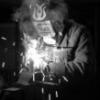
Stigian 1,234 #555 Posted May 14, 2012 Howdo all, today has been a day of contemplation and a bit of spanner/wrench work.. Pete and coffee contemplating the meaning of life, the universe, and hydro transmissions Being a "throw it all in a pile and work it out from there" kinda guy, my brain needs to know more than a few rough measurements to see if a second trans could be fitted up front. And thus a view from the front... It looks like might just fit!! Time to get serious.. I needed to see how far forward the trans would have to stick out the front.. So off came a few bits so the engine could be unbolted and slid back. The trans sitting roughly (if a bit high) where it should go. Not the best of angled photo's, the front of the trans would sit an inch or two forward for the front wheels. Quite a bit of metal would have to be cut out/moved about/welded back on to the front, but not too much work. And as she sits at the end of the day. Nothing that has been done so far can't be reversed with a bit of spanner work.. In a change from the norm, the wheel hubs came off the second trans with only a little fight.. Maybe a good omen Share this post Link to post Share on other sites
ol550 829 #556 Posted May 15, 2012 Wow! Have done a few out there projects, but not with so many helpful people watching. So I'll throw in a couple of thoughts. I do like the idea of the gear reduction for the brakes and it doesn't need to be on the drive axle or does it? I maybe should have commented earlier but not being an engineer I kept quiet and played the watch and see. My original thought with the belt drive was why not use chain and sprockets. I guess you could cut the pullies down and weld in sprockets. Chain would give a positive drive, alow you to put the brakes on any axle where there is room. The chain drive may also be necessary if you choose to go with the dual transmission setup to prevent you from going in circles from belt slippage. So you now know what was once on my mind and now on yours. Good luck, Mike Share this post Link to post Share on other sites
Horse'n Around 22 #557 Posted May 15, 2012 Wow Ian, Its awesome to see that after all your hard work your finally at the test drive stage. Great work! Ive been away for about 7 months and here... POOF, your driving it. Congratulations, you have made a ton of headway on it . Watching your progress is a true inspiration . John Share this post Link to post Share on other sites
jachady 130 #558 Posted May 15, 2012 It looks like the trans would fit in without a whole lot of trouble. I wonder about the linkages needed to get the motion control and brakes functioning. Plus you'd get to spend some more time on the lathe making a double engine pulley. :) Share this post Link to post Share on other sites
Stigian 1,234 #559 Posted May 15, 2012 Wow! Have done a few out there projects, but not with so many helpful people watching. So I'll throw in a couple of thoughts. I do like the idea of the gear reduction for the brakes and it doesn't need to be on the drive axle or does it? I maybe should have commented earlier but not being an engineer I kept quiet and played the watch and see. My original thought with the belt drive was why not use chain and sprockets. I guess you could cut the pullies down and weld in sprockets. Chain would give a positive drive, alow you to put the brakes on any axle where there is room. The chain drive may also be necessary if you choose to go with the dual transmission setup to prevent you from going in circles from belt slippage. So you now know what was once on my mind and now on yours. Good luck, Mike Hi Mike, yep there are a lot of helpful people watching this build, thank you all for the comments/advice over the years. I'd guess that reduction brakes would be best fitted as close to the diff as poss to give it the best chance of "doing it's thing" without having to cope with extra strain of the wheel to wheel belts. That was my thinking when I put the steering brakes at the back. The reason I went with belts rather than chains is belts are more "in keeping" with a Wh than chains, although the high cost of chains did put me off a bit. I'm hoping the new improved drive system will get rid of belt slipping problem, as the belts only really slipped when trying to turn and the brakes were not enough to get the diff to do it's thing. Tracks should help even more Wow Ian, Its awesome to see that after all your hard work your finally at the test drive stage. Great work! Ive been away for about 7 months and here... POOF, your driving it. Congratulations, you have made a ton of headway on it . Watching your progress is a true inspiration . John Thanks for your kind words John. It's almost driving, as long as you don't want to turn too sharply Lol, yep the past 7 months have been a bit busy on this project. It looks like the trans would fit in without a whole lot of trouble. I wonder about the linkages needed to get the motion control and brakes functioning. Plus you'd get to spend some more time on the lathe making a double engine pulley. A little slice here, a little slice there and the trans should fit. The motion and brake levers shouldn't be too bad to make work, just over sized levers with a big kink to clear the engine..... Well, the ability to have the machine turn on the spot ruled today. After many months of of building and trying different things and the brake steering still not working, I decided that I'd have nothing to lose and maybe everything to gain from trying John's twin trans idea. So with a certain pleasure the steering brakes were relocated to a cardboard box. Hopefully I won't be needing these again. The 6X6 looking more like a 1X1 Mr P dropped in to give me a hand with some cutting and moving the heavy trans about. Chopped! The best way I could think of to get the front trans in the right spot was to fit both rear axle extension thingys to the front trans and then bolt it all to the outriggers. Tomorrow the rebuilding the chassis around the trans will begin. I needed to find a nice thick bit of plate to make the front trans mounting plate.. Hhhmm... this should do the trick.. It might come in handy for giving the hood something to hinge on as well 1 Share this post Link to post Share on other sites
smoreau 658 #560 Posted May 15, 2012 Looking good! I like having the ability to spin your 6x6 in a circle like a Bobcat. You can use solenoid valves to control the front blade up and down to save you from getting long hoses made for a control valve like this. With the duel transmissions controlling this thing, you should have lots of pulling power with that twin kohler engine! I have played with the controls on the eaton 1100 and you can remove the cam plates and hook your control's right to the arm on the pump to get full forward and full reverse out or the trans. you could use some of the info from Matts foot control with the birds beak centering device to center the levers. Here is the link to Matt's foot pedal post. This is just to give you some ideas for your controls. Share this post Link to post Share on other sites
bowtiebutler956 649 #561 Posted May 15, 2012 Wow, you didn't waste any time tearing into it! Sounds like a great idea, I'll be looking forward to seeing it in action! Matt :flags-texas: Share this post Link to post Share on other sites
Terry M-(Moderator) 2,125 #562 Posted May 15, 2012 This machine just keeps getting better and better! Keep the pics coming! :handgestures-thumbupright: Share this post Link to post Share on other sites
jachady 130 #563 Posted May 16, 2012 How do you plan on disconnecting the non-drive sides of the transmissions? Share this post Link to post Share on other sites
bo dawg 477 #564 Posted May 16, 2012 I think there is way too much time on your hands. LOL! But I believe you just might pull it off. Keep up the good work! Share this post Link to post Share on other sites
meadowfield 2,545 #565 Posted May 17, 2012 How do you plan on disconnecting the non-drive sides of the transmissions? looking at the previous pics, I'd say a saw :D Share this post Link to post Share on other sites
Stigian 1,234 #566 Posted May 17, 2012 Looking good! I like having the ability to spin your 6x6 in a circle like a Bobcat. You can use solenoid valves to control the front blade up and down to save you from getting long hoses made for a control valve like this. With the duel transmissions controlling this thing, you should have lots of pulling power with that twin kohler engine! I have played with the controls on the eaton 1100 and you can remove the cam plates and hook your control's right to the arm on the pump to get full forward and full reverse out or the trans. you could use some of the info from Matts foot control with the birds beak centering device to center the levers. Here is the link to Matt's foot pedal post. This is just to give you some ideas for your controls. Hi Scott, that's a good idea using solenoid valves, Hydraulic hoses are certainly not cheap, so the shorter the hoses the better. Easier to route as well. Matt's "birds beak centering device" could come in very handy for the controls. Thanks for posting Matt's link and thanks Matt for posting it in the first place. Wow, you didn't waste any time tearing into it! Sounds like a great idea, I'll be looking forward to seeing it in action! Matt No time to waist Matt. The Ardingly show is getting ever closer. This machine just keeps getting better and better! Keep the pics coming! Thanks Terry. A few more pictures on the way. How do you plan on disconnecting the non-drive sides of the transmissions? By using Scott's neat diff trick at the top of this page. How do you plan on disconnecting the non-drive sides of the transmissions? looking at the previous pics, I'd say a saw Not sure I'd want to try cutting one of those rather hard axles by hand.. Might take a little while Not that much has happened on the project since the front got the chop. I'm not feeling full of energy at the mo so progress has been a bit slow. First job though was to get a top mount sorted for the trans so it will sit at the right angle to the chassis. So out came some unequal sided angle. Clamped to some box to keep all the parts level with each other for welding. Welded up, painted and bolted on. This will also hold up the trans oil filter and give the dipstick a bit of protection.. I think it should be strong enough To fit one of the non drive axles in the back next to the trans I'm going to have to throw the axle on the lathe and trim a bit from the inside. Luckily there is just about enough "un-needed" material to allow me to do this.. If it's still not quite enough space I can move the bearings a little bit towards the outside of the axle.. So it can be made to fit. Of course it goes without saying that I could not bring myself to do it the easy way and cut some off the trans axle!! Not quite sure where the battery is going to live now, the tray won't fit back in the spot it came out of! Oops, almost missed one! Share this post Link to post Share on other sites
Stigian 1,234 #567 Posted May 17, 2012 I think there is way too much time on your hands. LOL! But I believe you just might pull it off. Keep up the good work! Yep time is not something I'm short of (well apart from the Ardingly deadline), as I can't work this keeps the brain cells working and is also keeping me sane.. I think :) Share this post Link to post Share on other sites
massey 111 #568 Posted May 18, 2012 Ian, I admire your tenacity. :handgestures-thumbupright: Share this post Link to post Share on other sites
Don1977 604 #569 Posted May 19, 2012 Stigian you already hold the" World's Record for the longest Wheel Horse Modification". With Red Square's most read post You hold that record too. I hope that the second transmission will solve all the problems you have had with the brakes. I will hate to see this project end, but i'm pulling for you, Get Her Done. The "D Series" is no longer the biggest Wheel Horse , and they already built the electric "E series" so the your 6x6 should be the New "G Series". We are looking forward to more post and vidios. Share this post Link to post Share on other sites
COMMANDO6 20 #570 Posted May 19, 2012 I'd like to see Toro call Ian up and see about mass production... 1 Share this post Link to post Share on other sites
Stigian 1,234 #571 Posted May 24, 2012 Ian, I admire your tenacity. Thanks Massey, though it could also be blind stubbornness to get it done Stigian you already hold the" World's Record for the longest Wheel Horse Modification". With Red Square's most read post You hold that record too. I hope that the second transmission will solve all the problems you have had with the brakes. I will hate to see this project end, but i'm pulling for you, Get Her Done. The "D Series" is no longer the biggest Wheel Horse , and they already built the electric "E series" so the your 6x6 should be the New "G Series". We are looking forward to more post and vidios. Thanks Don, though maybe RedSquares most read post is due to the build dragging out so long! The second trans should do the trick, a pair of rubber tracks should make sure it does. Don't worry about this build finishing anytime soon.. Still loads to do once it is driving as it should.. Then there's always the next project to keep you all entertained I'd like to see Toro call Ian up and see about mass production... I'm up for that, as long as I get the correct royalty's of course Sorry for the lack of updates for a few day's, as you know I've been rather busy with something that has less wheels than the 6X6 but more clutch problems.. Quite a while was spent working how and where to run the new chassis rails at the front. Once I'd worked out a plan it was time for some more chopping up. Recycling is the name of the game. Not having a couple of lengths of box the right thickness and length I had to splice some bit's together. The smaller box inside will but the strength back. It was at this point that my ARC welder decided to give up the ghost once and for all.. It's had a few close shaves with a knackered switch in the past, but this time there was no coming back!! So out came the very old MIG to see what it could do.. Strong enough joining bit's of box, shame about all the welding splats from the gas-less wire. One of the new rails balanced in place. A nice large bit of flat plate would of come in handy for the "front of trans to chassis rails" bit. But as I don't have any it's time to make some.. Starting with this off-cut. Sliced, clamped and welded together. Er... maybe not quite welded together, I spot a crack in the weld! Turn it over and the other side was even worse!! I guess my MIG can't produce enough heat in the surrounding metal to stop the welds cracking when they cool The good news is a new ARC welder should be arriving tomorrow.. Anyway, here's a pic of the said plate roughly where it should be.. With a bit of trimming and tweaking.. I had a visit from Mark yesterday evening, and he came bearing gifts in the form of decals,Thank you Sir, they look great It was good to catch up again and natter about 'orses. And on to today's fun.. As I could not do any welding I had a look at making the rear left axle fit in the gap. A couple of coffee's and some measuring later, the plan was hatched. All I need to do is move the bearing block a 1/4" closer to the wheel hub bit. And trim 1/2" from the axle the other side of the block. Some gentle lathe work later.... It's almost in.. I just need to trim the thread down a bit and maybe turn a couple of mm's off the back of the castle nut just to make sure. Oh, and give this sleeve thingy a bit of a trim to fit onto the bearings. That's as far as I got today, this heat is knocking me sideways a bit! Oh, any of you fine UK chaps know where I can get any "used" conveyor belt from? I'm thinking it could be just the right stuff for making tracks out of.. Share this post Link to post Share on other sites
COMMANDO6 20 #572 Posted May 25, 2012 Nice, glad to see some progress! Share this post Link to post Share on other sites
Terry M-(Moderator) 2,125 #573 Posted May 25, 2012 The 6x6 decals are a nice addition! keep up the good work :handgestures-thumbupright: Share this post Link to post Share on other sites
Alan_Heist 7 #574 Posted May 30, 2012 Wow!! Been off RS for a while, and just got back signed in the other day. I started reading your thread 2 days ago in my free time, just finished... WOW!!! I have 2 questions though. 1. I know it started life with a gear shifted trans-axle, but then you switched it to hydrostatic drive. Now have 2 hydro's. Keeping period specific, it would be more appropriately called a Charger 20, as the hydro's of the era were Chargers, and the gear shifter's were Raiders. Just sayin'. 2. On the custom hubs... those are great pieces of machine work, but why didn't you just put the hubs on the other(out) side of the wheels? The 12" wheels are made to be reversibile, so they can track wide our narrow. Even though it's not done on WH's much, many companys used them in the narrow set-up. Or, was it so you would see the deep dish and not the back side of hubs. Seems like it would have saved you a bit of time and a lot of lathe work. Share this post Link to post Share on other sites
312Hydro 473 #575 Posted June 1, 2012 How's things going Ian? Any updates ahead? Share this post Link to post Share on other sites