Jump to content

Recommended Posts

Burnerman

I’m building a lowered 300 series wheelhorse. So far it’s a combination of 3 scrap tractors. 
the frame, trans and tins are from a GT2500 anniversary special given to me by a neighbor with a trashed Briggs. The Kohler M12 is from a junkyard 312 that was roached. The parts tractor I’m using for the build was another older 312. I’ve got the k301 in the garage. The trans was toast. Both axles wallowed out keyways and 1 axle actually broken. 
Anyway! I needed a project and a toy to putt around the neighborhood. I couldn’t find any other posts on how to do the whole thing. I’m trying to keep it cheap using stuff I have on hand and looking as “stock but cooler” as possible. So here we go. 
I’ll update this as I go along. 

  • Excellent 3

Share this post


Link to post
Share on other sites
 
953 nut
4 minutes ago, Burnerman said:

I couldn’t find any other posts

Guess you didn't look very hard.   @Ed Kennell, @fast88pu @wallfish and others have posted several.

  • Like 1

Share this post


Link to post
Share on other sites
 
Burnerman
3 minutes ago, 953 nut said:

Guess you didn't look very hard.   @Ed Kennell, @fast88pu @wallfish and others have posted several.

I read thru all of them. Thanks. 
 A lot of stuff missing and a lot of tin work. Also huge modifications to steering. The one thread the guy built it almost to the end and scrapped it, twice. 🙄
I’m trying to keep it easy and as simple as possible. 
 

  • Like 1
  • Excellent 1

Share this post


Link to post
Share on other sites
 
Pullstart

:banana-gotpics:


@giddyap has done a couple hot rods too

  • Like 1
  • Thanks 1

Share this post


Link to post
Share on other sites
 
Burnerman

I flipped the front axle and added stops for the steering and temporary plates to hold the front axle from moving. The reverse camber makes steering twitchy but manageable. A12D785E-63F5-4FEC-8CF0-E398EAA7D5C6.jpeg.7484f2f9cae6f2458bdd68199c30abb1.jpeg

I used spindles with a cotter pin to retain the spindles for now. 
I cut the backend off my donor frame. I drilled out the 4 threaded holes on the donor frame and bolted it to the top of the tractor frame. This raised the trans up to level it with the front. 7249414B-E8B9-480A-B8A5-874DBDB2F114.jpeg.c307d97427ae30ca07a2a27938519d4a.jpeg

I cut the stock trans mount off flush with the bottom of the frame. 

  • Like 1
  • Excellent 2

Share this post


Link to post
Share on other sites
 
Burnerman

 The brake linkage wasn’t gunna work now and neither was the clutch. I needed to get it setup like the 72 Commando 800 I have. Brake and clutch in one pedal. Then I have a bare floorboard for the foot throttle where the brake was. 
 The belt was the next issue. I basically copied the drive system on my Old Massey. I added a jackshaft behind the engine and using the short engine to jackshaft belt to clutch. The jackshaft to trans will just be a tensioned belt. 
 

886C94DF-905E-4633-8EE7-A8FCA9CB1FF9.jpeg

2B18C1F3-A84B-4B54-A05F-22DE296D1379.jpeg

D4A59833-2B3C-4BDF-873E-962FA2B7EE60.jpeg

  • Like 4
  • Excellent 1

Share this post


Link to post
Share on other sites
 
Burnerman

All of this will be hidden behind the stock tins. I’m not a body guy. 😁

  • Like 1

Share this post


Link to post
Share on other sites
 
 
Ed Kennell
3 hours ago, Burnerman said:

I flipped the front axle and added stops for the steering and temporary plates to hold the front axle from moving. The reverse camber makes steering twitchy but manageable. A12D785E-63F5-4FEC-8CF0-E398EAA7D5C6.jpeg.7484f2f9cae6f2458bdd68199c30abb1.jpeg

I used spindles with a cotter pin to retain the spindles for now. 
I cut the backend off my donor frame. I drilled out the 4 threaded holes on the donor frame and bolted it to the top of the tractor frame. This raised the trans up to level it with the front. 7249414B-E8B9-480A-B8A5-874DBDB2F114.jpeg.c307d97427ae30ca07a2a27938519d4a.jpeg

I cut the stock trans mount off flush with the bottom of the frame. 

This is exactly how I built mine.   Flipped the frame over, cut out the middle, and added another frame underneath.    Built a cross shaft clutch right behind the engine.  Flipped the axle over and mover the tie rods to the front.IMG_6568.JPG.ebf73efc7944bd57121c5f937b2a0203.JPGIMG_7084.JPG.539507e418c9acc85ae03b57f595aa4d.JPG


  • Like 8

Share this post


Link to post
Share on other sites
 
 
ri702bill

Nice work so far. With the front axle flipped, the weight is now on the spindle snap rings trying to pop them off - how did you address that?

  • Like 1

Share this post


Link to post
Share on other sites
 
Burnerman
24 minutes ago, ri702bill said:

Nice work so far. With the front axle flipped, the weight is now on the spindle snap rings trying to pop them off - how did you address that?

The first set of spindles had snap rings and pulled thru. The axle on my donor had cotter pins. For now I’ve just put a heavy flat washer under the cotter pin. Once I get all of the major stuff done I’ll go back and prolly drill and tap the spindles and add thrust washers and bolts to prevent them pulling thru. 
 I’m still in mock up stage so things change as I go along. Lol

  • Like 1
  • Excellent 3
  • Thanks 1

Share this post


Link to post
Share on other sites
 
SylvanLakeWH

:clap:

  • Like 1

Share this post


Link to post
Share on other sites
 
ri702bill
14 minutes ago, Burnerman said:

drill and tap the spindles and add thrust washers and bolts to prevent them pulling thru. 

Two things come to mind - if you make up a tap drill guide slipover tool out of aluminum or steel, it will allow you to drill the ends centered and straight - a piece of round or hex stock, perhaps 1 incn across by 1-1/2 long.In a lathe, drill thru with the tap drill, then counterbore one end 3/4" slightly oversize by 1/2" deep. You will need to remove the spindles to do this Drill both, go back to the lathe and tap it thru - it now becomes your tap guide.. Did this on the snout of a 6HP Tecumseh to accept a centrifugal clutch years ago - worked well.

Use blue loctite on the bolts at assembly.

  • Like 3
  • Heart 1

Share this post


Link to post
Share on other sites
 
953 nut

If you don't have a lathe to make your own center drilling rig just go to your favorite hardware store and look in the Hillman cabinets. Get a 3/4" ID bushing that will slip over the spindle and a 3/8' ID by 3/4" OD bushing.   The smaller bushing will be a press fit into the larger one and guarantee a centered starter hole using a 3/8" bit. Once the 3/8" hole has been drilled follow up with a 25/64" bit and tap the hole for a 7/16 X 20 bolt. 

  • Like 7
  • Heart 1

Share this post


Link to post
Share on other sites
 
ri702bill
1 hour ago, 953 nut said:

The smaller bushing will be a press fit into the larger one

What the Olde Time Machinists referred to as a "Honeymoon" fit....:lol:

Edited by ri702bill
  • Haha 4

Share this post


Link to post
Share on other sites
 
Burnerman

02E77846-A314-4074-99D5-E07C54239BAA.jpeg.134361de2798f5f71abb3899f073ce84.jpeg

Flipped front axle. The plates bolted to the frame hold the front axle from moving so it didn’t lift a rear tire cornering. 
89FB5F20-41CD-44B9-AB9F-099F3E05A517.jpeg.434e47300c80f7103afe41de3a77f682.jpeg

im going to cut out the 3/4” bar so the battery will fit in here. 
69324861-8691-4221-869F-C635A8AF9392.jpeg.a715167da94be9b69e76a7a1e3c1cc2e.jpeg

jackshaft and clutching links. The backside idlers are from mower decks. The pivot shaft is the old brake pivot shaft welded onto a deck tensioner arm bent to fit. I left that deck idler on. Lol

F53F8FA2-8B06-4779-96E0-FFEBC074B04B.jpeg.7169d0bbf3dd4f3cb373e3165a5346e1.jpeg

This is in the clutched/ brake locked position. 
57854471-E56D-49B5-BCE2-47098BF32ABA.jpeg.57efc480c1906a658cc5f8b060499e3b.jpeg

This is brake off clutch engaged. 
41754F02-F73C-4164-94DE-EF147182A344.jpeg.3b34363ac5c5dc25388b23ff3d668f60.jpeg

the fixed idler keeps constant tension on the belt. Also a deck idler pulley. 
0EC7CCDF-D748-495E-BD5C-3233FF63515F.jpeg.d5c43dd812308be2430e8aa23680878f.jpeg
I used the pto plate as a brake pivot. I need to drill a hole in it for the stock return spring to tension the belts. 
7016C6D0-62D3-441B-890D-3620D2C904CC.jpeg.e58eacd1580471943404982c071338c3.jpeg

The clutch/ brake linkage will all be hind the tin. 
F78A8965-B2B8-490F-8D8B-143D24BACF5E.jpeg.7bb9c84cef8b5f61078237af07a167d3.jpeg

I also realized there’s 2 diff ent style cast pedals. 
 

  • Like 2
  • Excellent 2

Share this post


Link to post
Share on other sites
 
Burnerman

AB0B9A73-ED7E-4E55-AE9B-D385008E02F7.jpeg
I used 3/4”x5/8” brass bearings in the clutch pivot. I have a bunch of 1” sq stock 1/8” wall I got for free. The bearings press in tight. I then used the 5/8” parking brake/brake pivot shaft as my pivot shaft for the clutch. I cut down a deck idler arm and welded it to the shaft after getting things aligned and belt tension/release figured out.

DED7D6FF-B161-438E-915F-FA03B58754C6.jpeg
then I cut the parking brake notches off and cut the ends off to use as bell crank arms. 

A3B5F371-A8D6-4772-B01A-68B864A9917E.jpeg
the brake shaft. 

277A2ED6-0E5E-42B0-94FF-15F2D2BD02C9.jpeg
everything needed to make a clutch pivot minus the deck arm

Edited by Burnerman
  • Like 1
  • Excellent 2
  • Heart 1

Share this post


Link to post
Share on other sites
 
Ed Kennell

F53F8FA2-8B06-4779-96E0-FFEBC074B04B.jpeg.7169d0bbf3dd4f3cb373e3165a5346e1.jpeg


You may have to add a belt pinching clip on the clutch pulley to stop the belt so you can shift without grinding gears.IMG_6894.JPG.54c0972e81e8a843bad03d65b31bf565.JPG


  • Like 3

Share this post


Link to post
Share on other sites
 
wallfish

I don't think you're going to find a complete "how to do everything". Even this build won't explain everything. Custom stuff like this is basically build as you go and use what works, scrap what doesn't. Make it yours, make it unique! Some stuff might not "look right" afterwards so change it. I've scrapped plenty of builds and ideas because they just didn't come out right. What's the point if it' ends up you're not happy with it?  Just do something you're proud of.

All of the steering components need to be tight. especially so at the tie rods. Some Toe In will tighten up some of the "twitchy" ness in the steering

Adding some Caster will help if the wheels start to shopping cart at higher speeds

Is that adjustable belt temporary? Or can it hold up to the forces involved? I've only seen those used for small electric motor applications.

Using a clutch idler on the inside of the belt loop allows for more belt slack to let it slip around the driven pulley for clutching. RJ58s used the idler on the outside of the loop so it can work but it's probably more difficult to dial it in to get it to work right.

:twocents-02cents:


  • Excellent 3

Share this post


Link to post
Share on other sites
 
Burnerman
Quote

You may have to add a belt pinching clip on the clutch pulley to stop the belt so you canshift without grinding gears.

I know I’ll have to do some tweaking with belt guides but because the brake is incorporated with the clutch; full pressure on the clutch will stop  the trans by applying the brake. 
it’s not a racer. There’s no shifting on the run unless your quick. Lol

@wallfish I copied the belt setup that’s on my 64 Massey Ferguson Executive 8. It clutches with a backside idler and the brake is separate on my year. It works fine. Also a clutch setup 
I want so bad to test it’ll out but I’ve got no where to sit. 😂

 The link belt is temporary. I use it to find the final belt that’s going to work. They are fairly durable if installed properly. We’ve go one on a hvac kicker unit with a 5hp electric motor. It’s been running with a link belt for 4 yrs now 24/7. 🤔 I should prolly check that unit tmw.🫢

 I understand everyone has a different build. I guess I’m trying to make building a cool Wheelhorse out of stuff that would otherwise get scrapped, cheap and easy. 
 

  • Like 1
  • Excellent 2

Share this post


Link to post
Share on other sites
 
Burnerman
Quote

All of the steering components need to be tight. especially so at the tie rods. Some Toe In will tighten up some of the "twitchy" ness in the steering

Adding some Caster will help if the wheels start to shopping cart at higher speeds

Thanks for the info. I had it up to 14mph before I dropped the rear and it was ok. 

  • Excellent 1

Share this post


Link to post
Share on other sites
 
wallfish
38 minutes ago, Burnerman said:

I guess I’m trying to make building a cool Wheelhorse out of stuff that would otherwise get scrapped, cheap and easy.

That's all I ever do. Buy as less parts as possible and try to get as many original parts on there as possible. Use the scrap pile!

Here's one from a while back

1514704501_2seater.jpg.bae36ffa9d736048ef18bea15f27145c.jpg

  • Excellent 4
  • Heart 1

Share this post


Link to post
Share on other sites
 
The Freightliner Guy

Did you make a golf cart out of a rj?

Share this post


Link to post
Share on other sites
 
Ed Kennell
1 hour ago, Burnerman said:

 building a cool Wheelhorse out of stuff that would otherwise get scrapped, cheap and easy. 
 

Congrats  on that.      And it is obvious you have the desire and skills to build a cool custom.    :handgestures-thumbupright:


In addition to old WH junke, I find a lot of use for old bed frames and scrapped weight training machines.

104_0696.JPG.844bf6c2254c93fcd7d3b96e1d17c30e.JPG

Edited by Ed Kennell
  • Excellent 2
  • Heart 2

Share this post


Link to post
Share on other sites
 

Create an account or sign in to comment

You need to be a member in order to leave a comment

Create an account

Sign up for a new account in our community. It's easy!

Register a new account

Sign in

Already have an account? Sign in here.

Sign In Now

  • Similar Content

    • Donavon
      By Donavon
      Need ideas to convert my 1054 A Frame plow into a snow blower
      Any idea's?
    • Wheel Horse 3D
      By Wheel Horse 3D
      Welcome, and thanks for visiting our vendor area.
      We got our start in 3D printing for customers right here on Red Square!
      If you'd like to see how every thing gets developed and the contributions of Red Square members, please visit the thread that started it all and browse through our progress to date.
      We love our clients' input and work closely to turn ideas into reality. If you have an idea, request, or questions, you can post to that thread, message us or tag us here on Red Square, or visit our Etsy store and reach out to us through there.
      Greystone 3D on Etsy
    • Wheel Horse 3D
      By Wheel Horse 3D
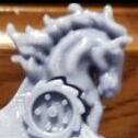
      Our customized ornaments have a base identical to our version of the original style ornament, but can be topped with 3 different styles of horse head and 3 different styles of wheel! Each is available unfinished, primed, or fully painted.
      They also include the pictured mounting hardware and the base spacer for a clean finished look. Can be ordred here Custom Wheel Horse hood ornaments..9 different styles


    • sjoemie himself
      By sjoemie himself
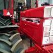
      A while ago I picked up a Canadiana 5hp heavy duty tiller. It features forward and reverse control and you could buy add on implements for it.


      My example unfortunately suffered a catastrofic engine faillure a.k.a. 'window' in the block. Hence it was cheap so I picked it up. The idea I had for it was to mount it on the rear of my 'Murray to IH 1568' build. However since I bought a Wheel Horse i've been thinking about mounting it on the front of that tractor.
      This is what i'm thinking..


    • giddyap
      By giddyap
      Featuring a WH plow frame a partial front frame and rear frames are attached. An inverted WH front axle and spindles are linked to a ross steering column. 8 speed and 301 Hemi Predator drive my extreme wheelbarrow tub custom Wheel Horse
×
×
  • Create New...