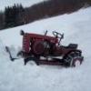
1973Auto 80 #1 Posted December 19, 2016 Hello all; Trying to fab a new frame at work and need the bolt pattern for the frame to the tranny for my 1973 12 hp auto, He is a pic from the old frame . Trying to fab a u-shape out of 1/4" and dont know if I have enough bolt clearence on the sides. Looking for the bolt patten on the tranny.Thank guys. Share this post Link to post Share on other sites
Ed Kennell 35,610 #2 Posted December 19, 2016 (edited) The bolts on my spare 3 speed measure 4.5" wide X 4" high. I can't guarantee your '73 auto is the same. but my understanding is they are all the same. Edited December 20, 2016 by Ed Kennell 1 Share this post Link to post Share on other sites
stevasaurus 22,229 #3 Posted December 19, 2016 You may want to re-inforce the frame from the inside, doing it on the outside will put the transmission back that much farther from the PTO shaft and will change how long your drive belt will be. Do some searches on this subject here, I know we have some good threads fixing this problem. Also, know that the bolts holding on the transmission do not go into the trans case. (blind hole)...at least the bottom ones are blind. 1 Share this post Link to post Share on other sites
1973Auto 80 #4 Posted December 19, 2016 Thank for the replies. This is the second time I have repaired this frame. It is on the inside. I have some pics from the past repair on my thread. I didn't have the frame attachment with me, I was hoping one of you guys had a diagram from an auto in your arcives. I just need to get thru the winter on this repair of the repair, so in the spring I can get a better an hope permanent fix. here is the original repair 4 Share this post Link to post Share on other sites
daveoman1966 3,586 #5 Posted December 19, 2016 This should help...template of the frame plate. I had the same issue a few years back and was able to reinforce the plate with 2 x 2 x 1/4" angle iron in each corner/side. This will NEVER come apart ! ! ! If you elect this method, work on one side at a time. Otherwise, calamity ensues. 5 Share this post Link to post Share on other sites
1973Auto 80 #6 Posted December 19, 2016 Looks like a plan!!! Thanks Share this post Link to post Share on other sites
Molon_Labe 731 #7 Posted December 19, 2016 Cracked mounts seem to be a common problem on these older Horses. On my 654 the transmission mount cracks on the transmission side were welded up and a 1/4 X 1-1/2 strap was placed across the front bottom of the transmission mount. I put the same strap on my C-101 and 416-8 even though they weren't cracked, a little insurance just in case, especially for the 416-8 since it pulls a 12" Brinly plow along with a 48" grader blade and a 36" tiller. 2 Share this post Link to post Share on other sites
N3PUY 1,031 #8 Posted December 20, 2016 My 416-8 had a destroyed mount plate when I purchased it. I don't know what the PO did to it but it was on a small farm. I straightened it, welded the cracks and plated the mount area with 3/16" steel. That moved the axle back a tiny bit but not enough to cause any problems. 3 Share this post Link to post Share on other sites
1973Auto 80 #9 Posted December 20, 2016 Basic question (don't have my manual in front of me) I'm drawing up a new bracket and need the bolt size that bolts into the tranny. Im thinking 7/16??? Share this post Link to post Share on other sites
pfrederi 17,128 #10 Posted December 20, 2016 3/8" 2 Share this post Link to post Share on other sites
1973Auto 80 #11 Posted December 20, 2016 THANK YOU!!! Share this post Link to post Share on other sites
Sarge 3,462 #12 Posted December 20, 2016 I've got the same issue with the old 1277 and it runs fluid filled tires , weights and chains on ags year round - this one is a hd worker . I've welded and reinforced the plate before and it's completely shattered this time , just metal fatigue and age being worked hard over it's life span . I plan to make the next plate from 1/2"HR steel and notch it into the frame to completely replace the original design and keep the original configuration due to how it's trans motion lever works , belt length and parking brake . The whole issue is how the trans tunnel bolts in there , very little room for the bolt heads to clear each other and I may go ahead and make them into square holes to use carriage bolts facing up into the tunnel to help with that . Leaves me more room to install heavier braces and address the trans trying to flex the back mounting plate/trans tunnel and dash stand - all of which have been cracked more than once . There is an incredible amount of leverage against all those parts when using a rear axle mount with a dozer blade - it causes the rear axle to try to rotate and constantly flexes that rear mounting area . This is why they added the angled braces on the rear of the frame but the material itself on the rear mount is too thin being only a bit over 1/8" . I'll try to do a detailed post in the spring about this for the older models , just have to wait for better weather . Sarge Share this post Link to post Share on other sites
1973Auto 80 #13 Posted December 20, 2016 Sarge: Yup, running into the same issue. Just trying to make this work until spring. Then I will re-do the bracket I have now with a 1/4" or 3/16" U-Plate that fits inside the frame. But I may not have enough room using the 1/4" for the bolt heads to fit in. If there is I may not have the room for a socket or box head wrench. Share this post Link to post Share on other sites
Sarge 3,462 #14 Posted December 20, 2016 I have that exact problem and had to use a line wrench open end to get onto the bolts to torque them . I'm hoping to change that issue using carriage bolts for the trans tunnel portion to free up some space - maybe even just plug weld some studs in there if I have too... Sarge Share this post Link to post Share on other sites
daveoman1966 3,586 #15 Posted December 20, 2016 (edited) When these frame plates crack, it is usually a 2-prong calamity. First, the plate is cracked at the corners and the second place is at the two lower mounting bolts. Very typically, the cracks / break-aways are BOTH at the corners and the mounting bolt holes. Fitting a 1/4" (or 3/8") square plate to the front of the original trans plate, then welding it at edges & bolting it in 4 places does not fully address the issue of where it cracks at the corners. You still have only 1/8" material at the corners and may very well crack again due to stress. For this reason, I opted to use the 1/4" angle iron, fit to shape and drilled for each side. This method adds 1/4" material to the frame plate for bolts, AND adds 1/4" to the corner, giving 3/8" corner material that will withstand enormous stress before cracking....if ever. A side benefit in just adding the 1/4" angle iron on each side....NO WELDING required. Just drill and bolt in. I used four 3/8" bolts on each side with Nylok nuts. Edited December 20, 2016 by daveoman1966 1 Share this post Link to post Share on other sites
Sarge 3,462 #16 Posted December 21, 2016 That's the reason I'm removing the original plate - it was too thin to start with to handle the stresses involved . 3/8"-1/2"HR plate steel should be fine and I plan to notch it into the end of the frame to end up at the same original distance and fully weld it solidly into the rear frame section . I wish the cast bosses in the trans case were a bit bigger to add at least two more bolt mounting points further away from the small pattern but the cases are too thin in those areas to do this mod the way I really want . I'm considering adding an additional cutout to go along the sides and not interfere with the motor section or any attachment brackets much like we use to reinforce trans/transfer case mounts in the off road trucks - sort of a cradle if you will . It would also help to strengthen the cast iron housing to stop any potential flexing which would shatter the cast material by spreading the force out across different points . Just have to wait until it's all stripped down and dive into it next spring when the weather is better . I'd like to tackle the same mount issue in the C series the same way since their pumps are much more powerful and they have a tendency to get worked hard . Maybe even come up with a plate kit to bolt or weld to frame...? Sarge 1 Share this post Link to post Share on other sites
Ed Kennell 35,610 #17 Posted December 21, 2016 Maybe the WH mechanical engineers had a plan when they designed the tranny/frame mounting plate as the "weak link". Much easier to repair these plates than to repair a tranny with stripped bolts or a cracked case. I am afraid beefing up these plates to the point where they no longer flex transfers the weak link to the bottom two 3/8-16 tapped holes in the tranny. Maybe the correctly designed bellville washers would be the way to take the fatigue causing flex off the mounting plates and bolts. Share this post Link to post Share on other sites
Sarge 3,462 #18 Posted December 21, 2016 It's not a bad point - cast iron makes for nice threads but they can pull out pretty easily - look the problems with Chevy heads and their rocker studs , lol... Loading washers could help quite a bit too - good idea . I'd still prefer to add more mounting points off the rear axles side bolts - it would sure help to spread the load further . Sarge Share this post Link to post Share on other sites