dells68 7,494 #1 Posted March 8, 2016 I'm at it again. I'm stumped -- doesn't take much!! My new GT doesn't seem to be charging. It's been switched to points ignition. First I thought my amp meter might be messed up, but I don't think so. If you turn on the lights or start it, shows hard discharge then returns to about 1 amp discharge. Never gone over to charge side. I started it several times yesterday adjusting idle and just riding. Went to start it and it barely turned over. First checked wires to rectifier and switch. Decided it might be the rectifier, so I tried one off of my parts tractor. Made sure it was grounded (directly to battery) and hooked up. Started tractor and the terminals got hot quick (same terminals as one already on tractor) , so I know the stator is charging. Could the two wires from the stator to rectifier be switched or does this matter? Center terminal goes to switch. Where else should I check? Sorry no multimeter to check voltage. Sorry so long - electrical ain't my thing, but I'm trying! 1 Share this post Link to post Share on other sites
pfrederi 17,147 #2 Posted March 8, 2016 The two wires. probably white from the engine to the rectifier are AC so they can be hooked up either way. Are you sure you have them on the correct rectifier/regulator terminals?? One of the terminals is probably marked B that goes to the ignition switch..the 2 from the engine go on the other terminals. Time to go by harbor freight / radio shack and drop 5-10 bucks for a multi-meter. 2 Share this post Link to post Share on other sites
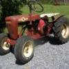
dells68 7,494 #3 Posted March 8, 2016 Just went to check the markings on the rectifiers. Can't find markings on either except for paint marks on the spare one (one that wires got hot on). Used top and bottom terminals for stator and center for switch - that's the way they were when I got the tractor. The wire from the rectifier goes to a terminal marked R on the switch - not B. Could the switch wiring be wrong? Below are pics of the spare rectifier. Share this post Link to post Share on other sites
953 nut 51,669 #4 Posted March 8, 2016 Since you changed the ignition to a points ignition I presume you had to change the ignition switch since the original one had a "M" terminal and the new one would have the "I" terminal. Did the charging system work prior to the ignition system change? We would really need to know what wiring diagram was used to be able to give a hand. Share this post Link to post Share on other sites
dells68 7,494 #5 Posted March 8, 2016 953 Nut I actually didn't do the conversion, it was done before I bought it. The switch has been changed along with what looks like a new starter solenoid. I traced the wires from the switch and have attached a crude drawing of the switch and corresponding wiring routing. Does this help any? Pfrederi, I'm going to pick up a multimeter next time I get to harbour freight - about 1hr 20min each way! Needed one on my 8n a few months ago, ended up rigging a light and two wires - 8n wiring seems simpler than this GT Share this post Link to post Share on other sites
953 nut 51,669 #6 Posted March 8, 2016 The wiring looks fine, my primary question was wondering if we had a component issue or a problem that had been there as a result of the rewire job. Share this post Link to post Share on other sites
dells68 7,494 #7 Posted March 8, 2016 So, it looks like it's probably a component issue then? Where should I look? Like I said when I tried the spare rectifier both wires from the stator got hot pretty quickly so I'm thinking the stator is working fine. I'm assuming the spare rectifier is probably bad judging by the heat issue and it still didn't charge. How would I check the rectifier and could it be a switch issue? Thanks for the help - like I said, I'm electrically challenged but I'm learning from you guys! 1 Share this post Link to post Share on other sites
953 nut 51,669 #8 Posted March 8, 2016 Once you buy that multi meter ( HF isn't the only place that sells them, try HD, Lowe's, Wallyworld etc.) you will want to check the stator output, should be 36 volts AC, probably is good, but need to be sure. Next I would hook it up to the old rectifier and see if you have a 14 volt DC +/- output; if not you will need a new one. If your output is good then try replacing the wire to the ignition switch before presuming it is the switch. Perhaps @Save Old Iron will chime in, he is the electrical guru around here. Share this post Link to post Share on other sites
gwest_ca-(File Mod) 10,496 #9 Posted March 8, 2016 Have the voltage regulator mounted on the tractor as the body of it needs to be grounded. Turn the key to the RUN position with the engine NOT running. Check the voltage across the battery terminals. Now move the red test lead to the DC+ terminal on the regulator. You should have the same battery voltage reading. If not fix that. Now move the black lead to the body of the regulator. You should have the same battery voltage reading. If not fix the regulator ground to the battery. Don't go away and leave the key ON. Garry 2 Share this post Link to post Share on other sites
dells68 7,494 #10 Posted March 9, 2016 Thanks guys! Stopped by lowe's and picked up a multimeter. Sadly, I have things going on the rest of the week. It may be Saturday or early next week before I get to test. I'll let you know as soon as I get a chance to check it. Share this post Link to post Share on other sites
dells68 7,494 #11 Posted March 9, 2016 Ok, Garry I couldn't lay down to sleep without going to check the battery voltage and the voltage in the + terminal on the rectifier. Turned on the switch. 12.56 volts across the battery terminals and about .04 or less volts (showing 0 most of the time) with the ground of the multimeter on the battery ground and the positive lead on the positive terminal on the rectifier. I replaced the wire from the switch to the + terminal on the rectifier with no change. I tried from the ground on the battery to the "R" terminal on the switch - still nothing. Does this mean the switch is bad or do I have a break in the circuit somewhere else? Thanks again for the help Share this post Link to post Share on other sites
gwest_ca-(File Mod) 10,496 #12 Posted March 9, 2016 There should be power at the ignition switch B terminal all the time. When turned to the RUN position the R terminal should have power. Sounds like the ignition switch has failed but to prove that theory run a jumper from the battery + to the regulator DC+ terminal or that wire. Check the voltage across the battery posts. Start the engine and see if the battery voltage increases as the engine runs. The starter will take a bit from the battery so it will take a few minutes for the voltage to come back up. Saw the picture you drew of the ignition switch terminals. Are they push-on or have a screw to attach the wire. If screws move the regulator wire to the A terminal if it has power in the RUN key position. Just another way of doing it. Don't leave the regulator temporary connection hooked up when you are finished. Does this switch have 4 key positions? OFF, RUN with Accessories, RUN and START A 3-position switch has OFF, RUN and START Garry 2 Share this post Link to post Share on other sites
ztnoo 2,298 #13 Posted March 9, 2016 (edited) After having some recent ignition problems on my GT 14, I can understand completely your frustration at getting your tractor to run properly. My problem turned out to be the coil + wire had come detached from the "I" spade on my switch. One thing I have noted from your pics is the overall corrosion on your rectifier. There is evidence of heavy oxidation on the rectifier body including the finning. That might point to a poor grounding of the rectifier body to the tractor as being a contributing factor to your problems. Make sure the mounting area of the rectifier body and the area of the attachment to the tractor are bare and clean to ensure a good ground. Solid state rectifiers don't typically fail, but it isn't unheard of. Typically other problems would be contributing to a non-charging situation. Also, those male spades on the rectifier are pretty funky looking to me, so I would suggest using a Dremel tool with a wire brush attachment, some steel wool, or some fine grit sandpaper to knock the corrosion off the male spades to be sure of good mechanical contact. Having clean posts on your battery and the male spades on your switch will help to make good physical, mechanical contact. Make sure there is some resistance when assembling male to female terminal connections. Anything that is loose or sloppy is a connection which is a potential trouble spot. Light application of dielectric grease will also help with electrical contact and long term corrosion protection. Edited March 9, 2016 by ztnoo 2 Share this post Link to post Share on other sites
dells68 7,494 #14 Posted March 9, 2016 Thanks guys! I'm taking a break at work before starting my lesson plans for next week (usually about a 4 hour process). I won't be back to work on the tractor until probably at least Sat. morning. I'm thinking the switch is probably messed up too. When I pull the keys out, there seems to be a copper wire that is wound around right inside the switch - should it be like that? I'll try to bypass the switch to see if it starts charging. I also plan on cleaning up the terminals they do look a little funky. The Rectifier I posted a picture of is actually my spare one and not the one on the tractor (it's got quite a bit of grease on it, so I'm guessing the grease has protected it The switch itself appears to be new and only has the off, run, and start positions with spade connectors on the back. I think I read somewhere else that the switch should have four positions for my PTO to function properly? You guessed it, the PTO doesn't work. If I do have to get a new switch, what number should I get? Screw or spade terminal type? Sources? Thanks again guys!!!!! Dell Share this post Link to post Share on other sites
ztnoo 2,298 #15 Posted March 10, 2016 If you determine you need a switch, here's a source. Seems to match your diagram. From iSaveTractors http://isavetractors.com/ignition-key-switch-for-garden-tractors-with-battery-ignition/ Share this post Link to post Share on other sites
Save Old Iron 1,563 #16 Posted March 10, 2016 if the regulator terminals are corroded or oxidized, chances are the terminals of the ignition switch are suspect also the battery voltage has to pass thru the ignition switch to the regulator compromise electrical connection anywhere along this pathway and you will loose the charge function 5 Share this post Link to post Share on other sites
dells68 7,494 #17 Posted March 11, 2016 Think I found it. Will have to wait till I can open the garage door to try to start it. Got home late from PTO at school and still had to go check. I can't stay away when something is bothering me. I checked the B terminal on the switch and only about .7 volts. New switch with nice clean terminals - shouldn't have been a problem, but the wire from the amp meter to the switch was not making a good contact. Pulled the spade off, pushed it back on hard and voila 12.6 volts at the B, R terminals and the B+ on the rectifier. I bet she'll charge now. I'll find out this weekend. Got our tractor club meeting tomorrow night or I'd check then. Wish me luck! 2 Share this post Link to post Share on other sites
dells68 7,494 #18 Posted March 12, 2016 Well, I checked my stator output at about 1/2 throttle - approx 31-32 volts. With switch off 12.56 volts in battery and at B terminal on switch. With switch on 12.56 volts on B+ terminal on rectifier. I checked all terminal connections and cleaned with 220 sandpaper. Cleaned terminals on the amp meter. With engine running, only 1 volt give or take across amp meter. Still not showing a charge. Battery isn't building up - now about 12.43 volts after starting and running 1/2 hour. Any ideas? Could it be the rectifier now? Still digging - love this machine and need to get it charging. Sitting inside the house, that Kohler just thumps away 2 Share this post Link to post Share on other sites
gwest_ca-(File Mod) 10,496 #19 Posted March 12, 2016 I would say you can now condemn the regulator. Batteries can do funny things to test results but your battery charger will bring it up so the tractor should also. The 1 volt across the ammeter terminals is normal. There is a shut resistor between those terminals and you are measuring the voltage drop across it. Garry 2 Share this post Link to post Share on other sites
dells68 7,494 #20 Posted March 12, 2016 Thanks Gary. I'll purchase one off of flebay. Does it matter that the new ones are 15 amp vw original 10 amp? Share this post Link to post Share on other sites
ztnoo 2,298 #21 Posted March 12, 2016 You might want to review the two threads I authored concerning rectifier replacements. PM me if you have more questions, if you think I can contribute to resolving your dilemma about this matter. Share this post Link to post Share on other sites
gwest_ca-(File Mod) 10,496 #22 Posted March 12, 2016 1 hour ago, dells68 said: Thanks Gary. I'll purchase one off of flebay. Does it matter that the new ones are 15 amp vw original 10 amp? Using a 15 amp is fine. The terminals will likely be a different configuration but that is OK because they will be identified. Garry 1 Share this post Link to post Share on other sites
dells68 7,494 #23 Posted March 13, 2016 Well, when I got home tonight I decided to pull my rectifier and have a look at it. Now I see why it wasn't charging. Pretty sure this piece isn't supposed to be broken in half. While there I pulled the tin off of the engine to trace down an oil leak that was getting on the cylinder fins. Ended up pulling the head to find oil on both sides of the head gasket. Going to clean up the piston, valves, and gasket surfaces before putting on a new gasket. Valves, cylinder walls, and piston look great. Now, I've gotta wait on parts to come to put it back together. Patience isn't my strong suit! 3 Share this post Link to post Share on other sites
ztnoo 2,298 #24 Posted March 13, 2016 Great pic!!! I assume that's one of the AC spades that has the intermittent..........? Share this post Link to post Share on other sites
dells68 7,494 #25 Posted March 13, 2016 Yup. Looks to be going to one of the spades for the AC current coming from the stator. I'm relieved to find the problem! On another note, I was shocked with the size of the piston in this thing - looks like something out of a Chevy 350 - no wonder they sound so good! 2 Share this post Link to post Share on other sites