Dieselcowboy 210 #1 Posted February 2, 2014 For the Hyd Specialist of you out there............The loader I have did not come with any hyd pump or feed or return lines. I had a new pump laying around and made the lines for what I needed. My problem I have is this setup up works kinda backwards. The slower rpm I run the engine the better / smoother the loader works. The faster I run the engine the more jerky and slower it seems to raise. We all know this is not good on an Onan. I have changed the fluid and it still is the same. One other note is I know I'm in the wrong on the return line which is smaller than the pressure. The factory port on the loader frame for the return line is very small. (Reason for smaller line) Only way it would work. Any ideas on what I could be have going wrong? Share this post Link to post Share on other sites
ol550 825 #2 Posted February 2, 2014 Do you have any way to check pressure? Your pumps GPM may be more than your valve can flow and you are poping the relief valve. Second thought is the suction hose large enough to feed the pump causing cavitation. 2 Share this post Link to post Share on other sites
oldredrider 2,547 #3 Posted February 2, 2014 Just guessing here, but is your pump rotation correct? Share this post Link to post Share on other sites
shorts 182 #4 Posted February 2, 2014 It sounds like your pump is starving for oil, probably either to arge GPM of a pump and or a restricted or to small of a suction line from the tank. look into the oil supply/suction line restrictions first, it is low pressure and should only have atmospheric pressure on it make sure it isn't sucking air or collapsing internally creating a flapper valve type restriction. if you have good oil supply try to balance your pump capacity with the size of the rest of the system, you might be able to slow the pump down by changing the pulley diameter, larger on the pump = less rpm = less gpm. your return line from the valve to the tank should be I line size larger than the pressure line from the pump to the valve and it should have relative low pressure and restriction 50 to 100 psi max. If you want to talk it thru send me a PM with your phone number and a good time to call. 1 Share this post Link to post Share on other sites
Dieselcowboy 210 #5 Posted February 2, 2014 The return does kinda worry me. I see lots of these arks on here with the return dropped in the top of the tank My factory return hole is about 6-8 in up from the bottom on the back side of the tank. It seems very small for the job. But the factory pump may only have required that and nothing more. Suction lines are 1/2in in size. and return is 1 size smaller. (I knew that wasn't correct from the get) But seemed like the only way I had without drilling another hole. I am guessing that my pump has way more butt than I need for this job. The larger pulley did help things in the beginning. Slower rotation . I am using a Webster pump. it has #'s on it but I really could not find anything on it for information. I'm not really sure what a relief valve feels like when it works. No way for me to know if it pops. Can someone explain what it feels or sounds like? Is it in the spool valve block? Share this post Link to post Share on other sites
ol550 825 #6 Posted February 3, 2014 Normaly the relief valve is part of the spool valve assembly. It will create a niose and vibration as well as warming the fluid. Post up the numbers on the pump as many times the numbers will tell the story. Share this post Link to post Share on other sites
Dieselcowboy 210 #7 Posted February 3, 2014 webster 59B1U2AEX-14 part#49908-24 Share this post Link to post Share on other sites
ol550 825 #8 Posted February 3, 2014 Your pump is a .59 cubic inch per revolution. That would make it about 8 GPM at around 3200 pump RPM. Need to figure how fast you are turning your pump. Any speed over 3200 would be over loading the suction capacity of the pump, providing it is not restricted in the plumbing. Share this post Link to post Share on other sites
Dieselcowboy 210 #9 Posted February 3, 2014 (edited) I have a 5 in pulley on it. so whatever size the pto on the tractor is. sry not at home right now. also I guess I was assuming that lines are ok being brand new. never assume any thing I know.... . but it does sound like the pump is about the right size. normally I can only get away with running 1000 to 1200rpm on the engine. that's it or the pump wines really loud. seems to get louder or strain the engine when I try to use the hyd. lift or dump our vise versa Edited February 3, 2014 by Dieselcowboy Share this post Link to post Share on other sites
ol550 825 #10 Posted February 3, 2014 (edited) Got any pictures? Your pump pulley will need to be larger than the pulley that drives it if you are to run at full throttle. Might have to go back to school to do the math if your going for exact, but I would bet a inch larger would be safe. Still need to be sure the suction side is large enough. Edited February 3, 2014 by ol550 Share this post Link to post Share on other sites
Dieselcowboy 210 #11 Posted February 3, 2014 If I become a supporter can I post pics again? If so I'll go to town posting them. Share this post Link to post Share on other sites
shorts 182 #12 Posted February 3, 2014 I've been doing some research on loaders today, the ark and kwick way manuals here don't give much technical information, mostly just parts schematics and part numbers, but with one of them gave the cylinder dimensions and another one gave cycle times of 5 to 6 seconds for a full lift, based on that info I ran some calculations and came up with a pump size of 6 gal/min or slightly less, this coupled with the line size appears to be about right. Assuming that Ole 550's info on your pump is accurate and it looks to be, you're pump is 8gpm and although it doesn't sound like much it's 25% oversize and the oil supply side of the system can't keep up with demand resulting in pump cavitation and excessive noise as it is starved for oil, continued cavitation/oil starvation will result in pump failure and contamination of the rest of the system with the debris. you need to slow the pump speed by 25% or replace it with a smaller pump. From your previous post this morning it sounds like the suction and return hoses are probably correctly sized for the rest of the system, just shooting from the hip here but 1/2 suction, 3/8 return and either 5/16 or 1/4 pressure lines should balance out the system. The return line into the tank below the fluid level is a good thing as it helps to eliminate splashing and introducing air into the oil. If we had some information about the control valve, make and model we could probably work that info to find out it's flow rates. Share this post Link to post Share on other sites
Dieselcowboy 210 #13 Posted February 4, 2014 If I were to use this pump how do I know what rpms I'm running at? I'm assuming that the advertised 4gpm is the 1/2" shaft turning at 1800 rpm? And is I were to put a 4 or 5in pulley on it , it would change the math? http://www.northerntool.com/shop/tools/product_200329712_200329712 Share this post Link to post Share on other sites
Dieselcowboy 210 #14 Posted February 4, 2014 I may take a cheap approach and see if a 7in pulley will fit in. See what that does to slow down the GPM. I'll keep you updated so everyone will know in the future. Share this post Link to post Share on other sites
shorts 182 #15 Posted February 4, 2014 According to the data sheet you want to turn the pump at 2400 rpm for 6 gpm, you need to know the diameter of the PTO puller and then do the math to find the rite pulley dia for the pump Share this post Link to post Share on other sites
shorts 182 #16 Posted February 4, 2014 Another tidbit of information on pulley sizes, we commonly measure pulley size by the outside diameter for ease of selection, but the engineers use what they call root diameter which is approximately where the center of the belt contacts the pulley, this tidbit should be taken into consideration when doing the math to properly match the pulleys for the proper rpm to adjust the max GPM of the pump. I don't have a current Grainger's catalog to check but they used to put a pretty good reference section with helpful tech info on hydraulics, belts and pulleys and chain & sprockets Share this post Link to post Share on other sites
Dieselcowboy 210 #17 Posted February 4, 2014 (edited) So basically a 1 to 1 would work on the pump I showed. I'm going to try to get some pics up to help with this. Its hard to guess when you cannot see the situation. Although you guys have come up with very good answers given the lacking information and pics. We have a graingers book at work. I'll be checking it first thing. Edited February 4, 2014 by Dieselcowboy Share this post Link to post Share on other sites
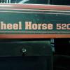
Dieselcowboy 210 #18 Posted February 4, 2014 (edited) Maybe this will help the effort. Some pics! Looks like a wh pto pulley is 4in (useing the outside pulley) and my pump drive is already 5in. That pump must be way more than I need here. I cannot fit the 7in in were I have it mounted now. Nor can I find one locally. Edited February 4, 2014 by Dieselcowboy Share this post Link to post Share on other sites
shorts 182 #19 Posted February 5, 2014 Look at the inside diameter of the supply/suction hose fitting, it looks like a standard R2 hydraulic pressure hose rated for 3000 PSi, the I.D. of some of those fittings can be very restricted, you need to use a low pressure hose with as large of an ID that you can get, think along the lines of something like a hose barb fitting used for heater hose and hose clamps, you will want to use a hose with some wire reinforcement so it doesn't collapse under suction from the pump, use 2 clamps at each end and offset the screws to make sure they don't let any air into the system Share this post Link to post Share on other sites
ol550 825 #20 Posted February 5, 2014 (edited) I would bet the smallest opening is 3/8 or maybe less due to the swivel fittings. Edited February 5, 2014 by ol550 1 Share this post Link to post Share on other sites
Dieselcowboy 210 #21 Posted February 5, 2014 I did use the same on suction and pressure hoses. 1/2 3500psi standard hyd hose. That could be the problem? Just not a large enough hole to pull oil to the pump ? Inevitably causing the loud chatter of cavitation in the pump. I really figured if I had too big of a pump the loader would just fly up and down from what I have read on other posts. I would bet the smallest opening is 3/8 or maybe less due to the swivel fittings. You nailed it down. 3/8 Share this post Link to post Share on other sites
Dieselcowboy 210 #22 Posted February 5, 2014 (edited) BTW I used that hose so I could put pioneer quick couplers on for a quick loader dismount without draining the system. It was my thought at the time anyway. I'm sure it can still be done with another larger hose. Do you think if I could get up to a 1/2 inlet on the suction line it might help? Looks like I could step up to 3/4 hyd line and keep my quick couplers. Or should I just do what I'm told and use the clamps and barbed fittings Shorts? Edited February 5, 2014 by Dieselcowboy Share this post Link to post Share on other sites
shorts 182 #23 Posted February 5, 2014 (edited) Use the hose and clamps, the QD fittings are the cats meow for pressure lines but they were never designed to be used on the suction side, they have internal restrictions and the design O-ring seals will allow air to enter. Look at your pump mounting bracket and re engineer it so the pump can be easily removed from the sub frame with the loader and the hydraulic system never needs to be opened up, Just remove the PTO belt and a couple of bolts or quick pins. Also look into using low pressure hose between the relief valve and the tank, low restriction and smooth easy flow will result in less turbulence and air being introduced into the oil as it goes into the tank Edited February 9, 2014 by shorts Share this post Link to post Share on other sites
Dieselcowboy 210 #24 Posted February 5, 2014 Thank you so much. I will be trying this system out. I'm glad I posts pics. You guys picked right up on a few things with a visual. Hard to explain and not leave out details. Share this post Link to post Share on other sites
Dieselcowboy 210 #25 Posted February 6, 2014 OK, this is what I am coming up with. We have a Napa store in the shop I work at so I use lots of their products. We have weatherhead hyd components available from them. My port sizes are 1/2 pipe at the pump and tank. So if I use a 1/2 pipe threaded fitting with barbs on one end (called field attachable) I can use a low pressure hyd suction line with an ID of 3/4. I realize it's not huge but in the end I will have a suction line with a bigger hole than 3/8. Hopefully I will be at 1/2" to 5/8" ID on the fittings. Also I will be removing the QD from the line when it's replaced and leaving the hyd intact when removing the loader. Would be the smart thing to do anyway as dirt in any form is not my friend in this case. Share this post Link to post Share on other sites