Jump to content
Sign in to follow this  
kpthorsefan

C141 snow/dozer blade

Recommended Posts

kpthorsefan

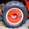
I have managed to find a snow/dozer blade off ebay for my C141, picking it up tomorrow. that means setting up the E tank again, and more spaying. it also comes with wheel weights and the bracket. i have been searching a long time for one of these now i have got one. :thumbs2:

dozerblade.jpg

Share this post


Link to post
Share on other sites
 
TT

Excellent find, Kevin!

Could you PLEASE get some close-up pictures of the wheel weights? :thumbs2:

(I moved this to the attachments forum)

Share this post


Link to post
Share on other sites
 
kpthorsefan

Excellent find, Kevin!

Could you PLEASE get some close-up pictures of the wheel weights? :thumbs2:

(I moved this to the attachments forum)

sorry never thought when i posted it. :thumbs:

I will take some close ups when i get it back tomorrow.

Share this post


Link to post
Share on other sites
 
WHC-125

Nice find and it looks like the wheel weights are stamped WHEEL HORSE :thumbs2:

Share this post


Link to post
Share on other sites
 
TJ

Excellent. I really like the wheel weights. :thumbs2:

Share this post


Link to post
Share on other sites
 
CasualObserver

Must be a special UK born weight? Those look really cool!!

Share this post


Link to post
Share on other sites
 
bitten

I want some of those wheel weights :thumbs2:

Share this post


Link to post
Share on other sites
 
kpthorsefan

I picked up the snow/dozer blade today, its all stripped down ready for the e tank her are some pictures of the weights, he also gave me some more bits he said come off a finger mower which he dumped because he said it looked dangerous so i missed out on that. Ps, what colour should the weights be painted, red like the tractor ?

PICT0327.jpg

PICT0329.jpg

PICT0330.jpg

PICT0331.jpg

these are the bits he gave me.

PICT0332.jpg

Share this post


Link to post
Share on other sites
 
kpthorsefan

I have made a start on getting all the rust off the snow/dozer blade, here are a couple of pictures. i also weighed the wheel weights, they are 25 Kg each and there is also a number moulded into them M 1302.

PICT0370.jpg

PICT0371.jpg

Share this post


Link to post
Share on other sites
 
d180man

Hi love the wheel weight can i have them! lol :thumbs: i like to find a set like them! :thumbs2: but nice find and keep up the photos! :ychain: :ROTF:

Share this post


Link to post
Share on other sites
 
kpthorsefan

The wheel weights seemed to have sparked a bit of interest, i take it they are original wheelhorse parts ? :thumbs2: also i have noticed i might have a peice of the frame missing, should there be a bar that links the frame to the lift arm on the tractor ? if so does anyone have a picture or the dimensions of it. its marked on this photo.

PICT0371-1.jpg

Share this post


Link to post
Share on other sites
 
TT

The wheel weights must have come from somewhere on your side of the pond and are the first ones I have ever seen with the cast name.

As for the lift link for the blade.....

3e67e2dd.jpg

If you want down pressure, you'll need to fabricate a link to go from the blade frame directly to the bellcrank arm where the chain is currently attached.

Share this post


Link to post
Share on other sites
 
kpthorsefan

The wheel weights must have come from somewhere on your side of the pond and are the first ones I have ever seen with the cast name.

As for the lift link for the blade.....

3e67e2dd.jpg

If you want down pressure, you'll need to fabricate a link to go from the blade frame directly to the bellcrank arm where the chain is currently attached.

Thats spot on tt :thumbs2: many thanks for the help, but when you say downward pressure how is it normally attached ?.

Share this post


Link to post
Share on other sites
 
nylyon

Down pressure is achieved by replacing that chain with a solid link. With a manual lift, the down pressure would be by holding the lift lever forward, with hydraulic lift, you get hydraulic down pressure.

Share this post


Link to post
Share on other sites
 
kpthorsefan

Down pressure is achieved by replacing that chain with a solid link. With a manual lift, the down pressure would be by holding the lift lever forward, with hydraulic lift, you get hydraulic down pressure.

Yes i am with it now, i see what you mean, that is a great help many thanks :thumbs2: .

Share this post


Link to post
Share on other sites
 
can whlvr

I made a solid link for 48 inch plow and its great for really scraping and digging,its around 12 inches long ,but im not sure,ill check later if needed.

Share this post


Link to post
Share on other sites
 
kpthorsefan

I made a solid link for 48 inch plow and its great for really scraping and digging,its around 12 inches long ,but im not sure,ill check later if needed.

That would be great if you could thanks :thumbs2: .

Share this post


Link to post
Share on other sites
 
CaptBob

I made a solid link for 48 inch plow and its great for really scraping and digging,its around 12 inches long ,but im not sure,ill check later if needed.

can whlvr,

I would be interested in seeing how you did a solid link as well. I was thinking of using "Height Control Rod part #110653" in place of the chain lift when using the dozer blade on my C-141 Automatic

CaptBob

Share this post


Link to post
Share on other sites
 
TT

Use a piece of flat steel to connect the hole where the trunnion for the lift chain eyebolt attaches to the bellcrank to either the hole in the "T" bar where the chain attaches, or fasten it directly to the tab on the blade "A" frame.

To get the correct length, install the blade on the tractor and place enough blocks under the cutting edge until you have about 1" of free travel left to pick the blade off of the blocks.

Move the implement lift handle to the fully raised position and measure between the two holes where the link will attach. Drill the holes in the flat steel and install with pins or bolts and you're done.

NOTE: Some models require a slight curve in the lift link to clear the steering support if you are attaching it directly to the bellcrank and the blade frame tab.

cb9bc073.jpg

Here's a photo of an OEM solid lift link:

7706link.jpg

Share this post


Link to post
Share on other sites
 
can whlvr

Thanks tt i have been really busy and forgot to respond to the other members, sorry guys that is exactly what i did ,the only thing i wish i had done was used pins with holes and quick attach pins instead of nuts and bolts,because when i want to use a mower deck i have to crawl under and take off side panels,so i decided it was easier to buy another tractor so i dont have to change the plow anymore. :thumbs2:

Share this post


Link to post
Share on other sites
 
TT

i decided it was easier to buy another tractor so i dont have to change the plow anymore. :thumbs:

I like your way of thinking! :thumbs2:

Share this post


Link to post
Share on other sites
 
kpthorsefan

Use a piece of flat steel to connect the hole where the trunnion for the lift chain eyebolt attaches to the bellcrank to either the hole in the "T" bar where the chain attaches, or fasten it directly to the tab on the blade "A" frame.

To get the correct length, install the blade on the tractor and place enough blocks under the cutting edge until you have about 1" of free travel left to pick the blade off of the blocks.

Move the implement lift handle to the fully raised position and measure between the two holes where the link will attach. Drill the holes in the flat steel and install with pins or bolts and you're done.

NOTE: Some models require a slight curve in the lift link to clear the steering support if you are attaching it directly to the bellcrank and the blade frame tab.

cb9bc073.jpg

Here's a photo of an OEM solid lift link:

7706link.jpg

That is brilliant, thanks TT. :thumbs2: i will be on to it at the weekend. And i must say a big :thumbs: to all of the help that i get from everybody.

Share this post


Link to post
Share on other sites
 
kpthorsefan

I know i am jumping the gun a bit, But i wanted to make sure it all fitted. there are still a few more bits to go on but they are still drying. here are a few pictures.

PICT0407.jpg

PICT0408.jpg

PICT0412.jpg

PICT0414.jpg

PICT0415.jpg

i had to make the short link, and still got to make the solid link.

PICT0413.jpg

had to cut out the rotten metal out of the plough head and weld a new piece in, and replace the scraper blade.

PICT0418.jpg

PICT0419.jpg

PICT0417.jpg

Share this post


Link to post
Share on other sites
 
kpthorsefan

I have now attached the swivel handel, had to make a new locking lever because the one that was on it was all bent out of shape with a slight mod to allow the rod to swivel, also replaced the metal wire linkages with 4mm steel rod threaded with lock nuts on the ends, also a spacer on the triangle linkage to space steel rod out from handle. and i think i am going to respray the frame/blade & weights red not to keen on the black.

PICT0438-1.jpg

PICT0450.jpg

PICT0455.jpg

PICT0452.jpg

PICT0443.jpg

PICT0440.jpg

Share this post


Link to post
Share on other sites
 
nylyon

Really nice. I love the rod conversion, makes the plow a lot more professional looking and something that Wheel Horse should have done to begin with! Very nice work.

Share this post


Link to post
Share on other sites
 

Create an account or sign in to comment

You need to be a member in order to leave a comment

Create an account

Sign up for a new account in our community. It's easy!

Register a new account

Sign in

Already have an account? Sign in here.

Sign In Now
Sign in to follow this  

×
×
  • Create New...