
Leaderboard


.JPG.9f2ecb26065c66527b0730084ab7fc7a.thumb.jpg.7dc8a04d9a53d44ee2b23f26ee94496f.jpg)
Popular Content
Showing content with the highest reputation on 03/26/2012 in all areas
-
2 pointsAren't they...usually anyway? :wwp:
-
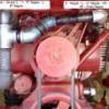
1 pointsince i posted pics of my 1057 with a solenoid for the starter generator, ive had a few inquiries about wiring diagrams and such to do this. well my 1277 without a solenoid became a candidate today because of many wiring issues and a burnt out switch. so i thought i would post a rundown on the install. the 1277 hasnt got much love since i got it xmas time, it gets moved around and thats about it. it had a few issues with wiring when i got it, but just havent had a chance to fix them and spend some time making it safe. well yesterday i went to move it and it was putting up a fight, wouldnt turn over very fast and started smoking from behind the dash. so i got the battery disconnected and left it alone until this morning. first of all i got the old wiring and switch out of there and got a few parts together to start on this. heres a few pics of what it looked like. cut wiring, bad connections and a bad switch. i already had disconnected the switch wiring before the pics.... better switch will be used to replace the burnt smoky one...... picked up some battery lug and ring crimp terminals for the 14 ga. wiring that i was going to replace. heres the solenoid i used. regular ford unit, around $7 from the local farm and fleet... first thing is to prepare the solenoid and work out where to mount it. i chose the same spot as my 1057, in behind the lift handle on the inside of the hood stand. one of the quadrant bolts is removed and replaced with a longer bolt so the solenoid can mount to it and a nut and star washer is used to fix the solenoid.. i needed to open up one of the holes on the solenoid bracket for the bolt to pass through, one fixing seems to hold it well enough. theres no moving around once the nut is tightened..... i didnt get a pic of the solenoid mounted up on the 1277, but heres the one from the 1057. same thing just ones a little cleaner.... then i moved on to making the battery cables. the battery in this is not the original style, that was a round post. im using this smaller different L/G post style battery and so the cables will be made to suit. i made the cables long enough so i could install either a left or right + handed battery. this tractor will be used with whatever battery is spare for a while, so i wanted to be able to use both orientations. now for this we need some 6 ga. cable and some wiring lugs. i used the crimp style with crimping pliers in a vise. ive made quite a few cables this way and it seems to hold the cable nice in the lugs. i worked on the bat+ to solenoid cable first. on a length of cable i put a lug on one end for the solenoid terminal post. i used the 'top' post for the battery feed and 'bottom' for the feed to the starter. you could do it either way as the solenoid doesnt care which one has the battery voltage. then measure the length for the cable and crimp the lug for that end. then i moved on to the cable that goes from the other solenoid post to the starter terminal.. and then made the neg side from the battery to the engine ground. heres the three cables done. used heatshrink on the terminals to protect the connection from the weather. now we move onto the 14 ga. wiring for the starter signal to the solenoid. since i was replacing the wiring that was bad, i also cut wire for the regulator bat circuit and cig lighter as well. these 4 wires were rough cut to 16 inches long. so we have 2 @ 14ga. red (for starter signal from solenoid BAT cable terminal to switch BAT+, and switch START terminal to solenoid S terminal.) 1@14ga. green (for ignition BAT+ to regulator BAT+) 1@14ga. black (for power from regulator L terminal to cig lighter) pic only shows 3 wires, just imagine theres a black one as well.... now use ring crimp terminals to terminate the wiring at the solenoid. crimping wire terminals...... first remove the outer cover..... then crimp using suitable pliers, i really like this style as it curls the tabs into the wire, rather than squashing them..... then when you are done make sure to heat shrink the ends...... both the red wires run to the solenoid. one wire will have a larger ring terminal to suit the larger bat post. the other will use a terminal to suit the S terminal on the solenoid. the wire that has the smaller terminal ( for the S terminal) mark the other end of it with a sharpie so we know this is for the S terminal. fix these two wires to the solenoid. now terminate one end of the green wire and one end of the black wire and fix to the regulator.... black to the L terminal, green to the BAT+ terminal. snake all 4 wires up through the grommet in the lower part of the dash and route over towards ignition switch area... the upper wire with the ring terminal is the wire to the coil + this was already in position. if you need to make a coil wire as well make sure to add this in so all wiring can be terminated and routed together neatly. i ended up cutting this terminal off and redoing it as the length wasnt right. cut a small piece of heatshrink tubing and place over all the wiring. once you have all the wires going to the switch neat and allowed enough room for the black lighter wire shrink the tubing to keep it in place so the lengths can be determined at the switch without individual wires moving. sometimes i will use zip ties for the same purpose. identify the red wire without the sharpie mark and the green and work out the length to cut to terminate at the BAT+ terminal of the switch. i used a 12ga. terminal for these two wires and crimped them together. now terminate the red wire with the sharpie mark to the START terminal and the coil + wire to the IGN terminal. also work out the correct length for the lighter wire and terminate. all these crimp terminals get heat shrink tubing over them. now i remove the wiring and making sure not to pull at it slowly snake it out from the dash and grommet and heat shrink the wiring into groups. the red wires going to the solenoid together, the green and black going to the regulator together and finally place larger heatshrink over the wires to the switch so that the lower end of the tubing covers the ends of the first two groupings of wire. make sure to do any crimp terminals with the tubing as well. now snake it all back into position and fix it all in place at the correct terminals.... at the regulator...... black to the L terminal, green to the BAT+ terminal. at the solenoid red with the large ring to the bat terminal that also has the cable from the battery + attached. red with the small ring to the S terminal on the solenoid. red and green terminated together to the BAT terminal of the switch. red from the coil+ to the IGN terminal ( this also takes one wire from the gen warning light) red with the sharpie mark to the START terminal (this takes the other wire from the gen warning light) black to the cig lighter. finish connecting the battery cables... one from the bat + to the large solenoid bat post (same terminal as one of the red wires) one from the other large solenoid bat post to the starter terminal. one from the battery - to ground on engine and/or other suitable place. just want to mention that two different batteries were used through this process. they had different post orientations. the first one has the + closest to the belt guard, the second has the + closer to the opposite side. hope this is easy enough to understand, not a real difficult job to do, just make sure your connections are good and you pay attention to where wires are meant to go. i used the colors off a factory wiring diagram, and used red for the solenoid signal which obviously wasnt on the factory non solenoid wiring.
-
1 pointI am wondering if I can or should load the tires on my LT1642 to grive me a little better "bite" when mowing, rolling and aerating. Is it really worth it? The tires have tubes in the and how do you pump the water/ washerfluid or liquid itno the tires? I was thinking about wheel weights but my model does not support nor offer them. Any insight would be much appreciated.
-
1 pointSomething else that also factors in and helps ease the pain of the gas bill for me is this. My son is 17, has a job and a car and still wants to go with his 'ol man to the show. He allready told his boss to not schedule him for those dates. He has been with me everyyear that I have gone. I think my first show was 2003 or 2004. We dont do as much together as he gets older but he still says "yep" when I ask if he wants to go and I really cherish that. I dont pressure him to go but keep thinkin every year that this is the last year he'll go. I still remember telling him at our second show how I wanted a pair of ag's and all he wanted to do was find em for me. He musta pointed out a dozen pairs for sale. I did end up with a pair that he found. So to me its well worth the $300 in gas to have some one on one chatting time in the truck, plus he can share the driving finally!!( so if you drive the same route as me ya better watch out for a black Dodge 2500 pullin a trailer with a crazy 17 year old behind the wheel goosing my HEMI and his dad fast asleep on the passenger side!!) Mike..........
-
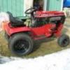
1 pointWell here is where I ended today. Just a pile of parts now. Now I need to get to sand blasting. Jake the cat loves the seat LOL
-
1 pointDid the guy offer an explanation or an apology? Without knowing the whole story, I can only guess he's about as mechanically inclined as a turnip! I'm no "super wrench", but even I can tell when things are getting hot and not sounding right. Sheesh! Duff :thumbs:
-
1 pointalright, i found a boo boo with the wiring of the gen light. first of all, i will try to explain the theory behind the light and why it does what it does. When you switch on the ignition, you get 12 volts to the gen light from one of the wires connected to the switch ign pole, and the other wire connected to the starter (generator) acts as a ground, so the bulb lights up. When you start the engine and its running, the generator gives out 12 volts and cancels out the 12 volts from the ignition switch that is lighting the bulb, so the bulb is now getting 12 volts from either side, (no ground) and goes out. if there is a situation where voltage coming back from the generator is very low or non existent, then the gen light will be lit in some capacity..... now comes the boo boo...... one side of the light is wired to the switch ign pole (ok) and the other is wired to the switch start pole (should be right), except this start pole wire is now a signal for the solenoid to jump the battery terminals and supply power to the starter. when the key is turned on we get 12 volts to the light from the ignition side and the other is grounded so the gen light is lit (good so far......) but when the engine starts and the generator is charging, theres no way for 12 volts to get back to the light from the other side as the heavy wire from the starter to the solenoid is now disconnected so the start function isnt operating. the other end of the gen light needs to connect to the solenoid battery pole that is connected to the starter. that way when the engine starts and the generator is charging (hopefully) the light is getting two sources of 12 volts and the light goes out..... as ive wired my 1057 this way as well, i have 2 tractors to get right.... these pics are a mix from the 1057 and 1277 and what i did to remedy this mistake, i wanted to edit my original post with this info but im not able to do that anymore. first pic ive disconnected the gen light wire that was connected to the start pole on the ignition switch. to this end i extended the wire by about 6 inches to make sure it will reach down to the large solenoid terminal that connects to the starter. heres a better view of the extended wire fed the wire through the dash and down to the solenoid. put the dash back together and you can see where the bulb holder for the gen light is, there is one wire going to the ignition pole of the switch and one wire is heading down towards the solenoid.. this wire heading down to the solenoid needs to be connected to the large terminal that feeds the starter.... im sorry if the original post showing the WRONG way to wire the light screwed anybody around..... im just surprised that some of you electrical guys didnt find it....... well, maybe nobody is reading this stuff anyway.... :ychain:
-
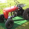
1 pointOK after a little closer inspection the 14.5 engine had an oil leak, the crankshaft seal was leaking some oil. Since it was leaking I just had to change the engine. It now has a 20 hp. Briggs twin and if I can find those extra exhaust pipes I have some where in my shop, I am planning on twin stacks on this beast. Those pipes bolt to the heads and run to the single muffler, one pipe on each side so it shouldn't be too difficult to fab a couple pipes. Looks better already. Found those pipes you know right where I wouldn't forget.
-
1 pointThe original idea for the Raffle to drive funds for Childhood Cancer Research cam from Tom Cornford who also is the caretaker for Max's tractor. Tom is donating the book he purchased in addition to his time and efforts. Since then, as you all are aware, Terry from ReDoYourHorse.com has been donating 5% of his sales to the charity drive, and I have also offered up my 2nd edition signed book should we reach our goal of $15,000! And Scott (whfan74) is also donating to the cause from the proceeds from his own personal show (it's too big to be called a meet 'n' greet) Since then we have had 2 more pleges of additional funds. Jordon from Jdog's Horse Ranch is going to donate 5% of his sales from the Big Show this year! I have met Jordon and his wife and can tell you they both are outstanding individuals. In a note that Jordon sent to me he said the following: "I have been thinking and it would kill me if my son was in Max's shoes" I couldn't say that better. I have a son too, and 2 daughters, and I couldn't imagine them (or any of your children) having to go through what Max had to endure. No parent should. Michael Martino, the author of Straight From The Horse's Mouth, A Wheel Horse Story has also upped the ante by donating not one but TWO brand new FIRST edition books signed by Cecil and himself. You all know just how rare these books are and it is likely that an opportunity to obtain a BRAND NEW signed first edition will NEVER come around again. But wait, there's more: Michael is working on a 3rd edition, and will be giving ONE copy of the 3rd edition book when it is available. If you haven't purchased your chance to win one of these treasures, what are you waiting for? Go to the Shop now and buy your chance for only $10 and you will have the opportunity to own one of these near priceless treasures, but mostly to help put an end to Childhood Cancer!
-
1 pointYou can get aftermarket here http://www.rcpw.com/search/?quest=390420&search.x=0&search.y=0 Chas
-
1 pointTony, my irregular heart beat kicks in everytime I pull my 4x8 flat bed and one tractor 100 miles round trip with my Poncho. Granted I have 126K and climbing but I've pulled with it since 28K. That 3800 and wrong wheel drive tranny never was comfortable pulling from day one. Plus..... you're going to a tractor show.... you can't be taking the getto machine (I'm not).... you need to take the "Man" machine. :ychain:
-
1 pointEither that or they buy Hellmann's Mayo by the gallon !!
-
1 pointpics
-
1 pointFor some reason I feel very small right now.....lol
-
1 pointSo here we are again – the merry band of ‘D’ owners and the like . I’ve noticed from some posts that I’ve made that few are prepared to put their head above the parapet when it comes to hydro problems though to be fair some have taken the trouble to offer me what help and advice they can. I’m certainly no expert but having spent hours studying the Sundstrand manuals and diagrams (and for what it’s worth) here are my thoughts on the subject and feel free to shoot me down in flames for anything I get wrong here…… For my sins perhaps I have two tractors with hydrostatic transmissions – a ‘C’ and a ‘D’ Automatic transmissions are notorious for the fact that they are less efficient than a manual counterpart. In short, a small but significant amount of the energy from the engine gets lost in the transmission and never makes it to the rear wheels. Energy lost in this way is converted to one thing – HEAT. The Sundstrand is no different in this respect and I can hear the extra effort that the engine of my C-120 has to produce when I take the parking brake off which also engages drive to the hydro pump even when the tractor is not moving anywhere yet. This heat is dissipated via the casing of the pump which has fins to increase the surface area and also through the transaxle casing which also contains hot oil. The C-120 has a crude fan as part of the drive pulley to help with the cooling process. The transmission on my C-120 runs noticeably cooler since cleaning all of the greasy dust that builds up and lowers the efficiency of the fan itself and also removing the similar grease and grass cutting dust that covers the cooling fins on the pump unit. It still runs much hotter though than the manual transmission in my C-100. Cooling for the pump on a ‘D’ is provided by the air being drawn into the engine as part of the engine cooling system. It’s easy to see any greasy debris on top of the pump unit but I found lots of it between the fins on the underside of the pump that’s only easily accessible when the tractor side panels are off though you can sort of inspect it from underneath the tractor. The other potential cooling issue I found on the ‘D’ was that the little holes that form the flywheel grille mesh where air is drawn into the flywheel fan were pretty blocked up in fact they were far worse than I had thought from an initial look. Both the engine and hydro pump cooling systems must have been impaired as a result. I didn’t find much stuff in the actual engine cooling fins but it’s worth taking the tin off to check. What I’m basically trying to say is that although the cooling systems on a ‘C’ and ‘D’ are different they are both important and help to keep the oil temperature lower than it would otherwise be. Even multi-grade oil gets thinner the hotter it gets though the effect is less than with single weight oil. Having got the cooling system as good as it gets then if loss of power as the oil heats up is still an issue then pressure is being lost somewhere. Low oil pressure as an automobile engine heats up sometimes points to a worn oil pump but more usually indicates worn crankshaft / big end bearings. When the oil is cold and thick the pump can keep up with the loss but when the oil gets hot and thin it can’t. The problem in a hydrostatic transmission is that the loss of pressure caused by oil bleeding from the high pressure circuit to low can happen in a number of places. I believe you can check the main charge pump with a pressure gauge but as the pump in a ‘D’ also powers the lifts which are on a different circuit then it can be pretty much eliminated if the lifts continue to function normally when lifting a load even though the motive power is poor. If the loss is in the drive system only, then it could be happening in the pump unit behind the engine or it could be happening in the motor unit on the transaxle. Unfortunately you could swap out the pump only to find the fault is actually in the motor. As Jeff suggests it could be due to worn / scored parts in the pump (or motor) particularly if it affects both forward and reverse. However, it could also be caused by a poorly seating valve. Some valves are linked specifically to forward or reverse – if the ailment affects one direction only then one of these is a likely suspect - the case with my D-200. If it affects both directions then it could even be a poorly seating push valve. When they are working well they’re great – when they don’t work properly they can be a real pain! I'm not sure I'd want to try using a heavy single weight oil which would be ok during warm weather but incredibly thick in very cold weather. I think as a first step down this route I'd try 20-50. It would only be marginally thicker in the cold (20 weight) but have the properties of a 50 weight oil when hot. Well done Jeff for being prepared to have a go at a hydro - I'm looking forward to seeing some pics. As I said earlier - feel free to shoot me down on any of this but it's up for discussion. Andy
-
1 pointYou guy's are just thinking with the wrong head...cylinder head that is
-
1 pointNope Ken... all the round hoods are indoors....


This leaderboard is set to New York/GMT-04:00